
Variability system and analytics for continuous reliability in cloud-based workflows

a cloud-based workflow and variable system technology, applied in software maintainance/management, instruments, data processing applications, etc., can solve problems such as affecting customer experience, introducing defects into the program, and creating problems for customers

Active Publication Date: 2019-11-05
INTUIT INC
View PDF13 Cites 10 Cited by
  • Summary
  • Abstract
  • Description
  • Claims
  • Application Information

AI Technical Summary

Benefits of technology

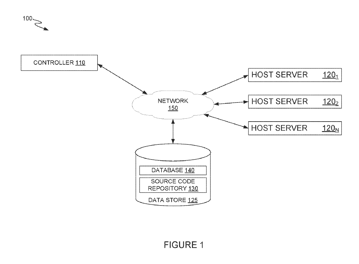
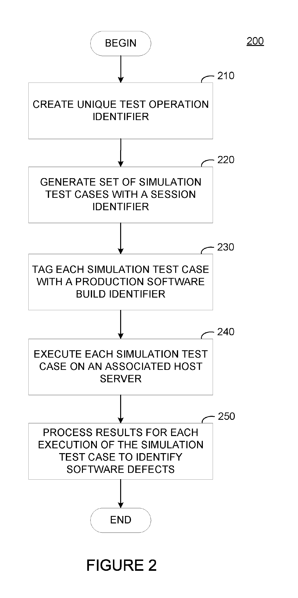
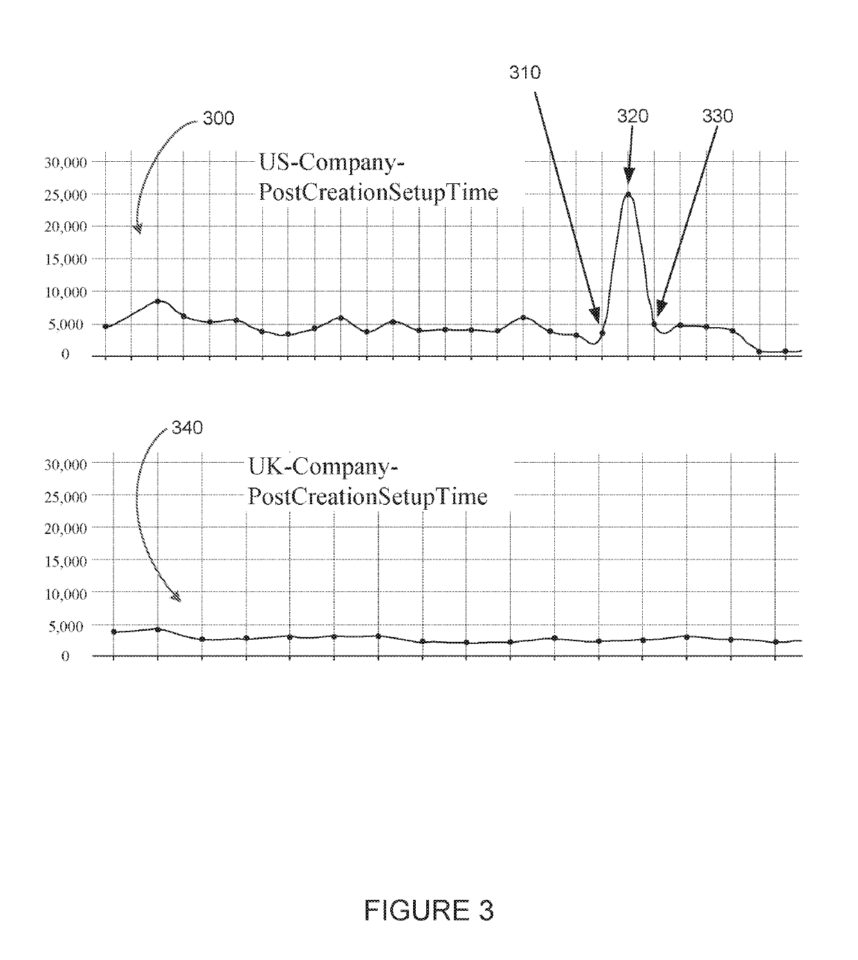
The present invention provides a method, computer-readable storage medium, and processor for detecting and sourcing software defects. This involves comparing an output data set from a host server executing a test operation in a software system to a performance model and identifying any deviation in the output data set that exceeds a threshold. The test system then retrieves a source code update that was committed to a source code repository before the test operation and compares its scope to the defect. If the source code update matches the defect, the test system notifies the development team related to the source code update about the error in the source code update. This helps to improve software quality and efficiency in identifying and addressing software defects.

Problems solved by technology

A problem with such distributed independent development teams is that defects can be introduced into the program when the individual teams each update the portion of the source code they are responsible for updating, maintaining, and developing.
The defects introduced by the independent updates often are not discovered until they degrade the performance of the production software, creating issues for customers and negatively impacting the customer experience.
Reviewing the numerous independent source code revisions is very labor intensive, requiring either a large number of developers to be devoted to the project or allowing the defect—with the associated customer issue—to persist for an extended period of time.

Method used


Image

  • Variability system and analytics for continuous reliability in cloud-based workflows
  • Variability system and analytics for continuous reliability in cloud-based workflows
  • Variability system and analytics for continuous reliability in cloud-based workflows

Examples


Embodiment Construction

[0013]Generally, developers of commercial software applications can utilize a public cloud architecture to deliver continuous global access to software products. Applications deployed via a public cloud architecture often include many subsystems that work together to provide the services to users. In one example, a cloud-based application can serve separate user interfaces to users based, for example, on a location of the user. Each of these interfaces may implement region-specific variations on various features. For example, while generating invoices for purchase orders may use similar inputs, the generated invoices may differ based on tax regulations in different geographical regions. To allow users to generate invoices that comply with regional regulations, each regional interface can provide application functionality using region-specific processing rules and common subsystems that need not be region-specific.

[0014]Commonly, the individual components, or modules, of the software...


PUM


Abstract

The present disclosure relates to automatically detecting software defects and determining the source of the defect. An example method generally includes receiving an output data set from a host server executing a test operation and comparing the output data set to a performance model. A test system identifies that a defect exists in software executing on the host server based on determining that the output data set deviates from the performance model by more than a threshold. The test system retrieves a source code update from a source code repository that was committed to the source code repository before the execution of the test operation. The test system compares a scope of the source code update to the defect and notifies a development team related to the source code update of the defect upon determining that the scope of the source code update and the defect match.

Description

BACKGROUNDField[0001]Embodiments presented herein generally relate to quality control testing and defect detection in software applications, and more specifically to performing quality control testing concurrently on multiple software deployments.Description of the Related Art[0002]Commercial software is increasingly being provided using distributed architectures through public and private cloud computing environments to global customers. These software products can includes common programming subsystems and individualized program components for specific customers, markets, regions, etc. Commonly, developers work in teams devoted the creating and maintaining a single subsystem or individualized component. Thus, many development teams work in parallel to maintain the program, but with minimal inter-team communication. A problem with such distributed independent development teams is that defects can be introduced into the program when the individual teams each update the portion of th...

Claims


Application Information

Patent Timeline
Patent Type & Authority Patents(United States)
IPC IPC(8): G06F11/36G06Q10/06G06F8/20
CPCG06Q10/0639G06F11/3692G06F8/20G06F11/3612G06F11/3676G06F8/71G06F11/3419G06F11/3684G06F11/3688G06F2201/81G06Q10/063
Inventor CHATTERJEE, SHREESHANKARBALASUBRAMANIAN, POONGUZHALI
Owner INTUIT INC
Learn More