Thermal morphing anisogrid structure

a technology of anisogrid and morphing, which is applied in the direction of mountings, optics, instruments, etc., can solve the problems of increasing the cost of the system, requiring the rigid primary structure to be very heavy, and difficult to replicate the system in orbit to create a large coherent mirror, etc., to achieve significant mass savings, cost savings, and reduce the output of the given inpu

Active Publication Date: 2019-11-12
THE UNITED STATES OF AMERICA AS REPRESENTED BY THE SECRETARY OF THE NAVY
View PDF9 Cites 0 Cited by
  • Summary
  • Abstract
  • Description
  • Claims
  • Application Information

AI Technical Summary

Benefits of technology

[0013]Optionally, the thermal control element is configured to selectively increase temperature of a first clockwise helical member and a first counter-clockwise helical member by a minimum controllable amount, and to simultaneously decrease the temperature of a second clockwise helical member and an a second counter-clockwise helical member by the minimum controllable amount, thereby causing a minimum amount of displacement between the top interface constraint and the bottom interface constraint.

Problems solved by technology

These rigid primary structures are required to be very heavy.
A key problem is phasing the photons from each individual telescope back together to create an effective single optical surface.
Replicating this system in orbit to create a large coherent mirror is difficult.
The development of this thermally stable extremely stiff primary structure introduces significant mass requirements that increase the cost of the system.
The conventional actuators used in hexapods are not able to provide sufficient control capability to achieve the high precision morphing capability.
Furthermore having the actuator as the primary load path reduces the stiffness of the system relative to the invention reducing structural performance.
The hexapod is also not structurally efficient and has some dynamic complexities due to the kinematic nature of the design.
Conventional systems, with a single solid primary (monolithic) mirror, are limited by spacecraft volume and mass as well as the exponential scaling of mirror manufacturing costs.

Method used


Image

  • Thermal morphing anisogrid structure
  • Thermal morphing anisogrid structure
  • Thermal morphing anisogrid structure

Examples


Embodiment Construction

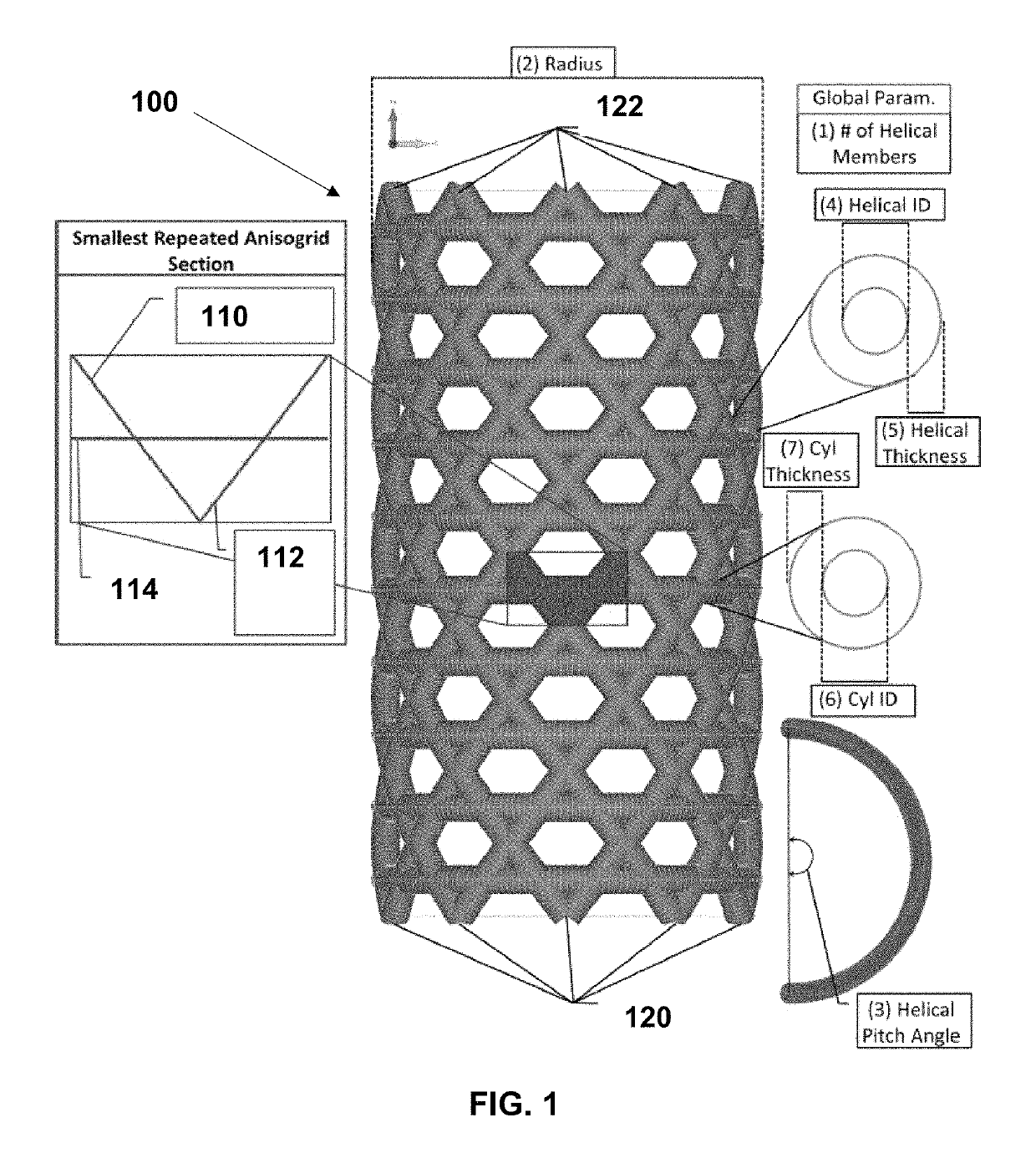
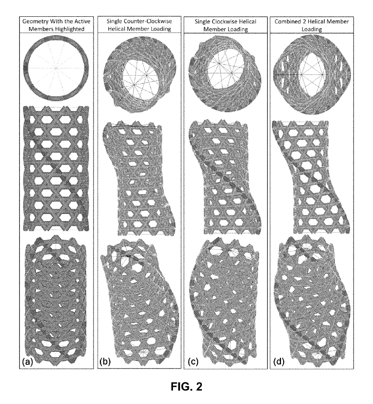
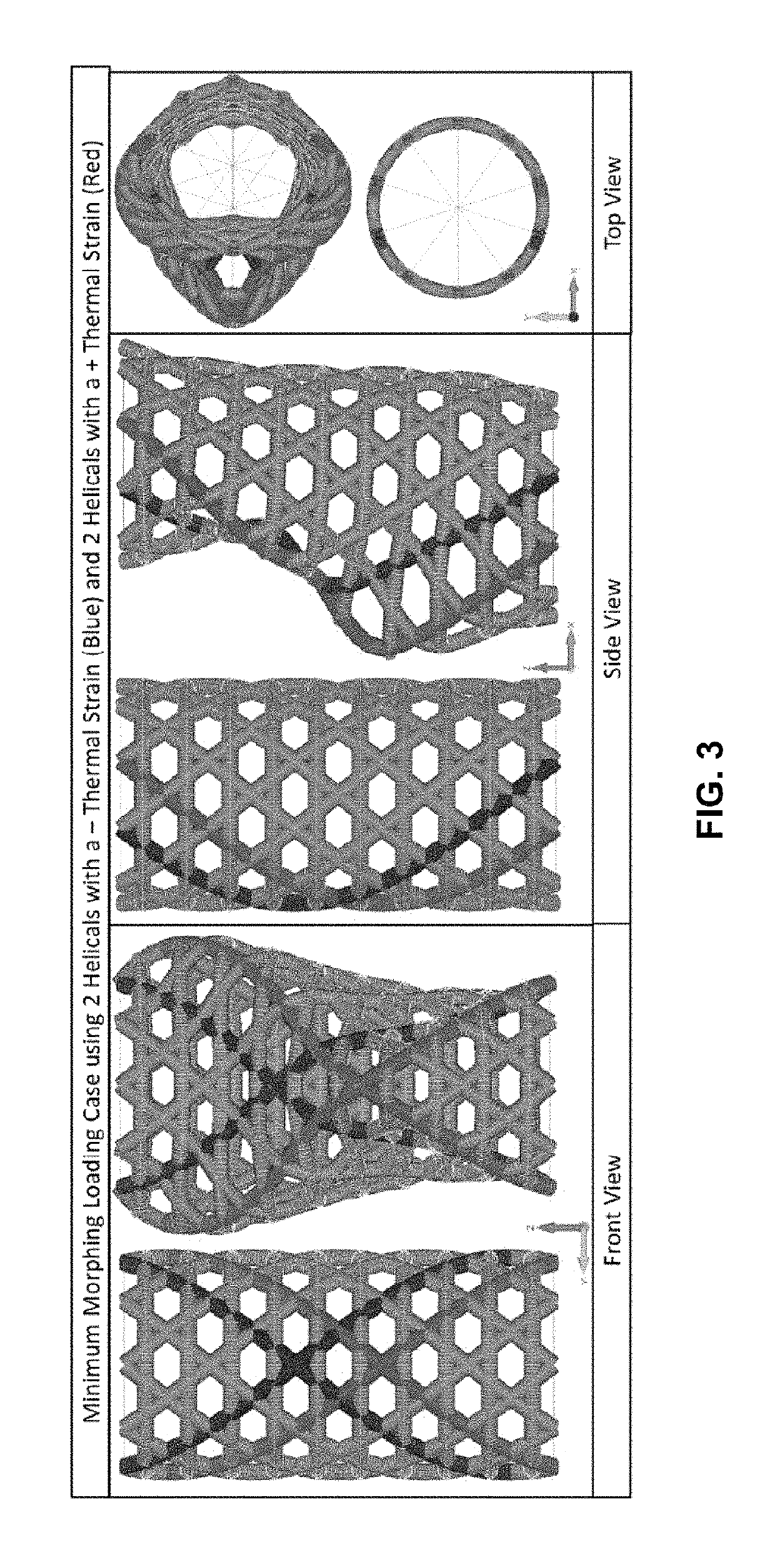
[0028]Exemplary thermal morphing anisogrids, illustrated in FIG. 1, may replace conventional structural paradigms, which consist of a heavy and rigid primary structure coupled with a secondary morphing system by using smart adaptive primary structure. This is achieved by integrating the adaptive capability directly into the primary structure. The adaptive structural concept achieves design requirements by predicting and adapting to thermal and structural loading environments in real time. This adaptive capability is achieved through the use of thermal strain as the active actuation mechanism to control the lengths of helical members in the anisogrid structure. To morph to the desired position, thermal energy is applied to the helical members in the system to generate axial expansion due to local and global thermal strains, which pushes and pulls the system into the desired configuration. The application of thermal loads can be seen in FIGS. 2-4. While thermal strains have been propo...


PUM


Abstract

A thermally-controlled actuator includes a cylindrical anisogrid structure formed from a plurality of circumferentially offset clockwise and counter-clockwise helical members, and a plurality of longitudinally offset cylindrical ring members. A thermal control element is configured to control the temperature of at least some of the members. The cylindrical anisogrid structure has a top interface constraint and a bottom interface constraint, and the thermal control element is configured to control a displacement of the top interface constraint relative to the bottom interface constraint via control of the temperature of at least one of the helical members.

Description

RELATED APPLICATIONS[0001]This application claims the benefit of U.S. Provisional Application No. 62 / 457,529 filed Feb. 10, 2017, and U.S. Provisional Application No. 62 / 477,215 filed Mar. 27, 2017, which are each hereby incorporated herein by reference.FIELD OF INVENTION[0002]The present invention relates generally to thermally-controlled actuators, and more particularly to thermal morphing constrained structures such as the anisogrid.BACKGROUND[0003]Conventional structural paradigms consist of a heavy and rigid primary structure coupled with a secondary morphing system to achieve the displacement control required for high precision applications. These rigid primary structures are required to be very heavy. Terrestrially, sparse apertures, such as the Navy Precision Optical Interferometer (NPOI), exist. The NPOI uses six telescopes, mounted to bedrock, placed along three 250 meter arms joining the light to create a single image with much higher resolution than is capable to achieve...

Claims


Application Information

Patent Timeline
Patent Type & Authority Patents(United States)
IPC IPC(8): F03G7/06G02B26/00
CPCF03G7/065G02B26/00G02B7/1827
Inventor PHOENIX, AUSTIN
Owner THE UNITED STATES OF AMERICA AS REPRESENTED BY THE SECRETARY OF THE NAVY
Why Eureka
Try Eureka