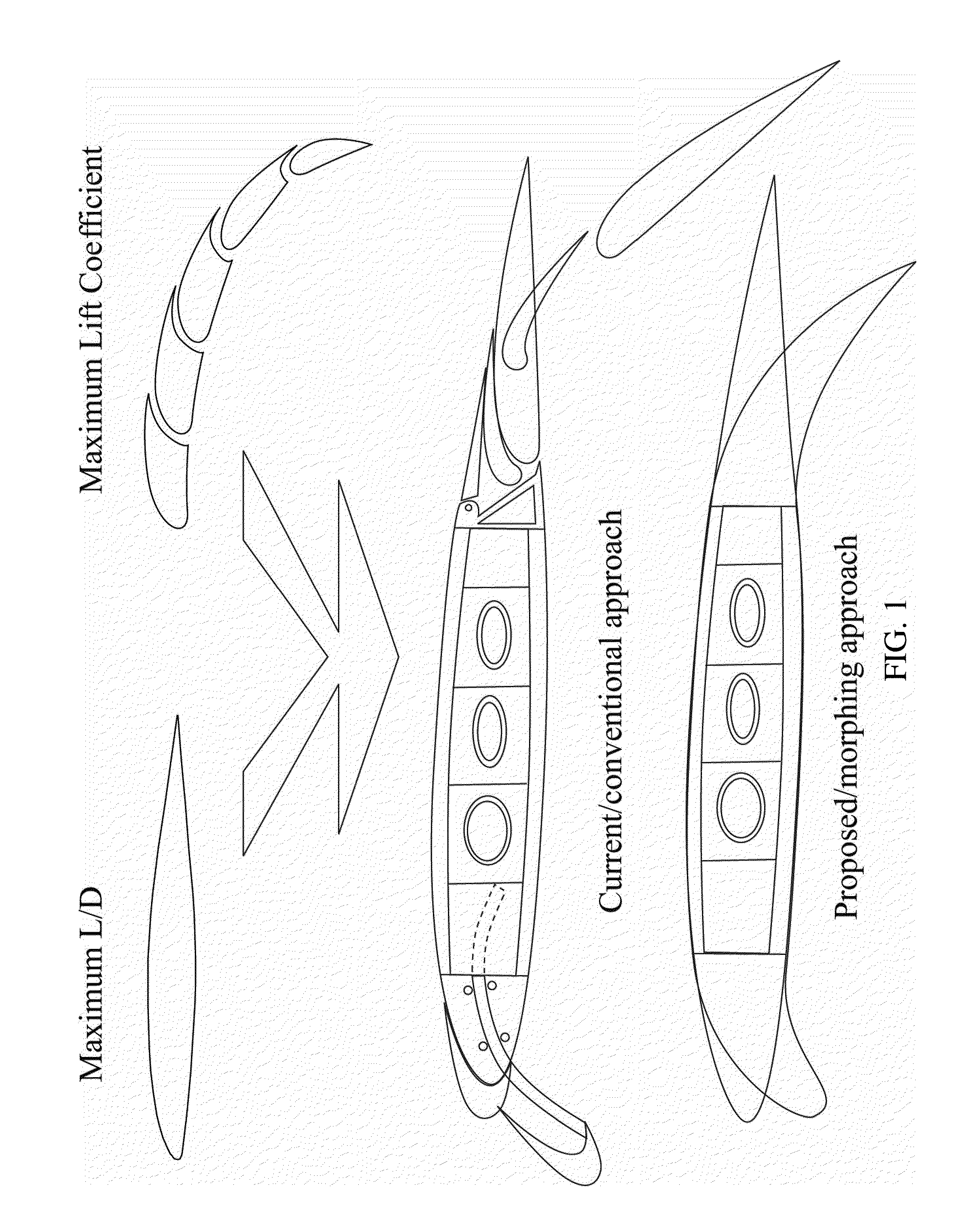
However, present-day
high lift devices still rely heavily on complex mechanisms that consist of thousands of individual parts and heavy actuators to displace and / or rotate the whole
assembly.
Matching the performance of bird morphing in combination with a low weight / energy / complexity penalty has proven to be very challenging.
Morphing wing design is especially challenging because its multidisciplinary nature impacts each of the individual groups or categories directly.
For example, a swing wing can be beneficial from an aerodynamic standpoint; however, it also comes with a weight penalty and requires a completely different structural arrangement, which impacts the production and
stress engineering groups.
However, few of the morphing technologies have transferred to the civil realm of
aviation.
They can exhibit great strains and apply considerable force.
However, they generally exhibit a large power draw due to energy dissipation and their
hysteresis can amount to 38%.
Moreover, their bandwidth is generally poor because of thermal saturation issues [5].
Although these designs accomplish large deformations the structure of multiple parts, hinges, and actuators is complex and occupies most of the internal wing volume.
Piezoelectric materials have a lower single-
stroke work density than SMAs and generally a limited
stroke and force capability.
Although their energy densities are high, their low
transfer efficiency requires a relatively large amount of energy to actuate these materials.
In addition, the actuators are relatively slow.
However, they typically do so in a discontinuous way, requiring hinges or tracks to rotate and displace individual wing components.
A result is that systems of
high lift devices are complex, heavy and often maintenance intensive.
However, in subsequent years, aircraft designers abandoned this concept in favor of hinged control surfaces which required less force to deflect.
During a stall, the boundary layer cannot cope with the large adverse pressure gradient and detaches from the airfoil surface, leaving a turbulent flow wake.
This causes the lift to drop and the drag to increase.
Sweeping the wing backwards to increase the drag
divergence Mach number has had an
adverse effect on the low-speed lifting capability of the wing.
In addition, LSAs are highly
cost sensitive, which makes the addition of a complicated high-lift device less attractive.
Thirdly, while the Airbus aircraft used supercritical airfoil sections, the older Boeing designs (737, 747, 767) used modified airfoils from previous designs with some form of supercritical technology.
This requires extremely stiff and strong components within the extend / retract mechanism, which generally results in a significant weight penalty.
The flap
system complicates the wing's
trailing edge structure and introduces electrical systems in relatively thin parts of the wing.
Furthermore, the
system adds weight to the wing and increases the cost of manufacturing.
The
steep slope of the pressure gradient is an indication that the boundary layer will separate at a lower
angle of attack than for the thick airfoil, giving rise to an abrupt drop in lift.
Even though the mechanism could work well, the structure lacks an integral torque box that is essential to provide appropriate levels of torsional stiffness.
Even though the flight tests demonstrated advantages of the wing morphing, there were significant drawbacks to the way the morphing was achieved.
This resulted in a relatively heavy and complex actuation
system.
Although effective in providing significant wing deformations and smooth transitions, compliant mechanisms are often much more complicated than the control surfaces they are replacing.
At a certain
angle of attack, the bubble bursts, no re-attachment occurs, and a sudden drop in lift results.
It was already shown in the 1950s that modification of the
nose of a 35
swept wing could result in significant changes in maximum lift coefficient.
Because adaptive flaps are integrally attached to the main wing, they do not benefit from the jet effect that exists when a flap is slotted.
In addition, they lack any Fowler motion.
Membrane wings, however, do not have the torsional and
bending stiffness that is required for larger UAVs and manned aircraft and the morphing techniques pioneered on these small aircraft can therefore often not be extrapolated to larger aircraft.
Because they penetrate the flow, a
disadvantage of the VGs is the increase in profile drag during
cruise.
It also induces a significant increase in pitching moment because of high aft loading.
Extracting this energy from the airstream rather than from actuators reduces the size and consequently the weight of the wing-movable.
The main drawback of twist-active wings is that there is should always be a trade-off between torsional stiffness on the one hand and
actuator sizing on the other hand.
Other disadvantages include (a) the added structural weight that is required to bear the torque load that is introduced by sweeping the wing, (b) reduced flap effectiveness, and (c) a spanwise drift over the wing that increases boundary layer thick-ness and leads to increased drag and reduced
aileron effectiveness.
However, this leads to other inconveniences like added structural weight to bear the
bending moment of the wing and less volume for
fuel storage.
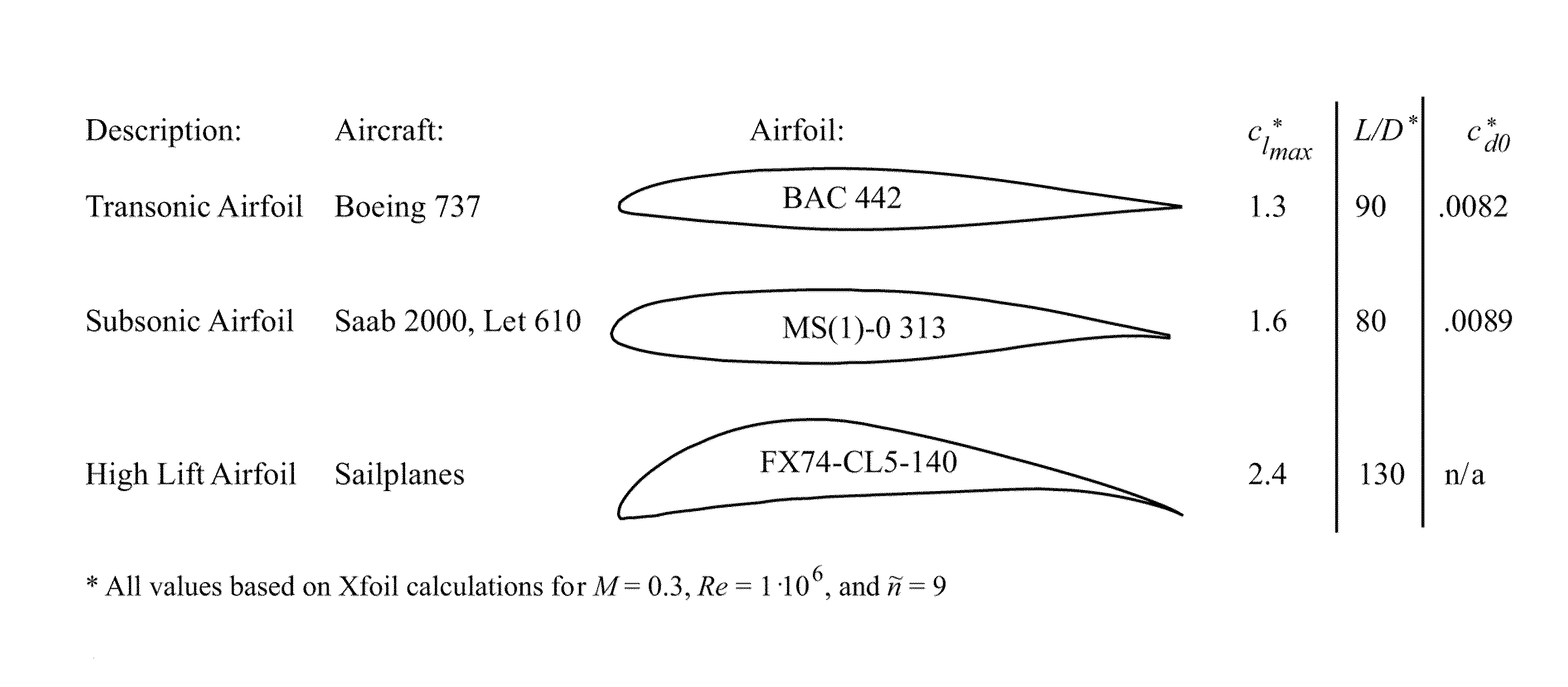
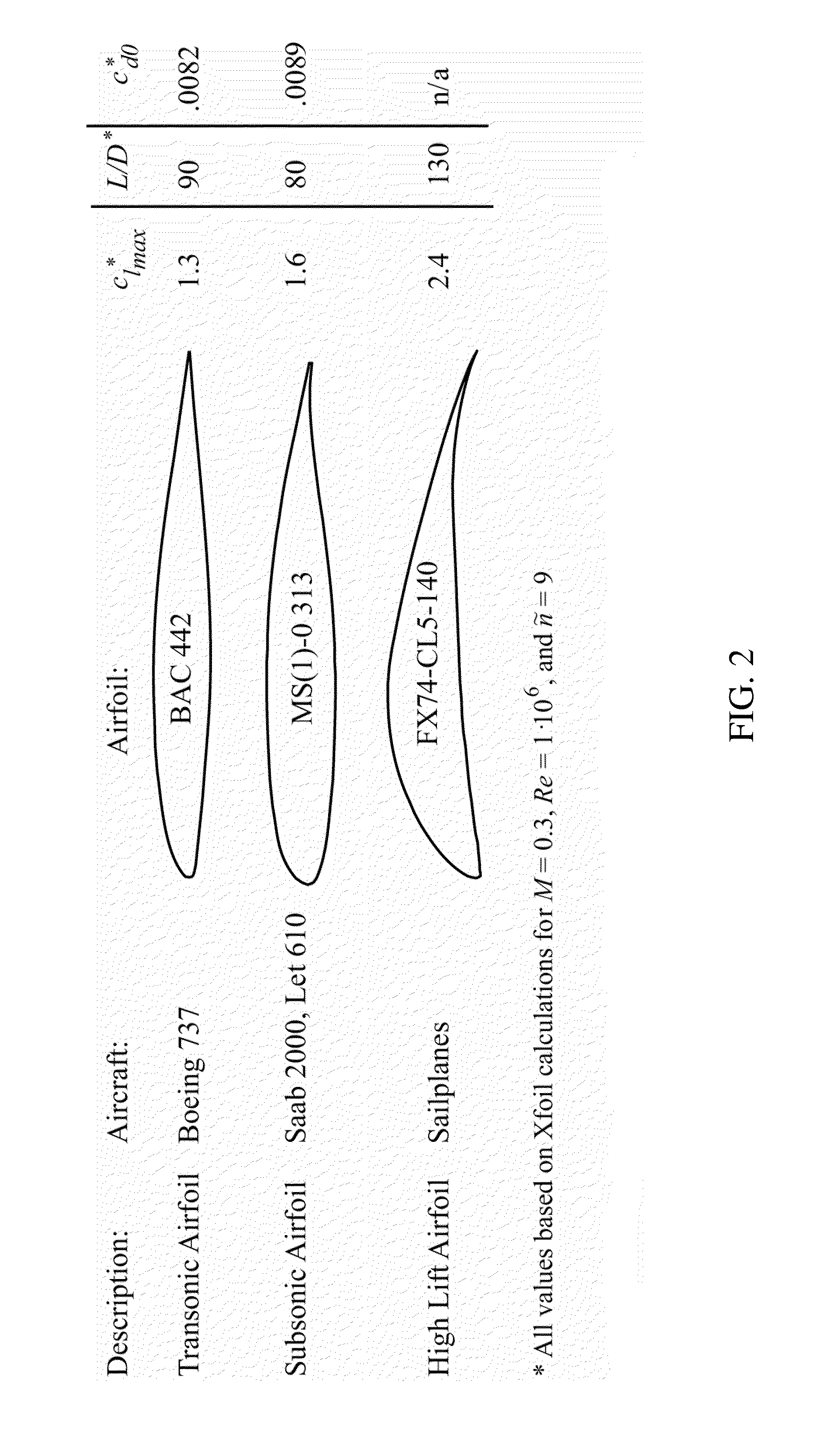
Furthermore, in Section 2.2.2 it was shown that thin airfoils generally have worse high-lift characteristics than thick airfoils, which require higher take-off and landing speeds.
Even though the effectiveness of this wing was excellent, penalties in terms of complexity and the impossibility to store fuel become clear.
In addition, the complex wing structure in combination with the requirement of powerful actuators led to a very
high weight penalty.
Wind tunnel tests successfully demonstrated the morphing mechanism, but were inconclusive about the expected drag reduction at
transonic and supersonic speeds.
It might be expected that interference-drag penalties occurring in folded position negate the drag reduction due to increased effective sweep and decreased wing area.
Therefore, morphing structures have been limited to the
high lift devices such as flaps and slats.
However, due to insurmountable weight problems associated with the swing-wing mechanism Boeing discarded this morphing concept in favor of a fixed
delta wing.
The project was cancelled before one prototype was built due to heavy opposition by (among others) environmentalists.
The
morphing wing concepts which were conceived for military applications (e.g. F-111, F-14 and F-18 AAW) are therefore unsuitable for commercial applications.
Maintaining such structures can be costly and is, therefore, unattractive for commercial airliners.
Other disadvantages such as the limited ability to store fuel in the wings or a
complex control system have prevented morphing technology from transferring from the experimental military aircraft to modern transport aircraft.
As was mentioned before, because adaptive materials have not been certified for use in primary or secondary aircraft structures, applying them on commercial aircraft is still impossible.
Commercial applications of morphing structures can only be viable if certifiable systems (including certifiable materials) are used, direct operating costs are decreased, and
structural integrity is maintained.
At airports which are situated at higher altitudes (e.g. El Alto International Airport, Bolivia, m) the colder temperatures would reduce the maximum lift capability due to the limiting deployment of the temperature-
active structure, while the lower density would amplify this effect due to a decrease in lifting capability.

