Catheter incorporating a curable polymer layer to control flexibility and method of manufacture

a polymer layer and polymer technology, applied in the field of catheters, can solve the problems of inability to manufacture the entire shaft using coextrusion technology, change in flexibility, and limited shaft design, and achieve the effects of less stiffness, increased rigidity, and increased flexibility

Inactive Publication Date: 2005-12-22
BOSTON SCI SCIMED INC
View PDF77 Cites 8 Cited by
  • Summary
  • Abstract
  • Description
  • Claims
  • Application Information

AI Technical Summary

Benefits of technology

[0022] In a preferred embodiment, the catheter shaft further comprises a selectively curable region adjacent to at least one flanking region. In a preferred embodiment, at least a portion of the curable region can be irradiated with ultraviolet light from an ultraviolet light source to selectively cure that portion which is irradiated. Preferably, the flanking regions can be shielded from at least a portion of the ultraviolet light by at least one ultraviolet shield. According to a preferred embodiment, exposure to ultraviolet light emitted from an ultraviolet source cures the curable region. Curing the curable region alters the stiffness of the catheter shaft.
[0026] According to a preferred embodiment, the stiffness may be varied along the length of the catheter shaft. Preferably, the stiffness may be varied by the amount of curing done along the length of the catheter shaft. For example, it may be desirable for a catheter shaft to have increased stiffness near the proximal end and less stiffness (more flexibility) near the distal end.

Problems solved by technology

This method requires substantial manufacturing steps to assemble the various sections and makes it difficult to manufacture the entire shaft utilizing coextrusion technology.
Further, the shaft design is limited by the predetermined flexibility characteristics of each section and can include relatively abrupt changes in flexibility at material changes.

Method used


Image

  • Catheter incorporating a curable polymer layer to control flexibility and method of manufacture
  • Catheter incorporating a curable polymer layer to control flexibility and method of manufacture
  • Catheter incorporating a curable polymer layer to control flexibility and method of manufacture

Examples


Embodiment Construction

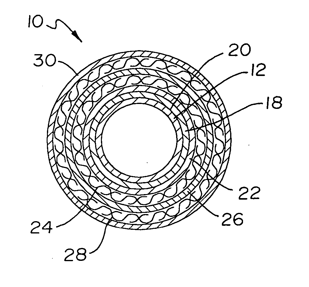
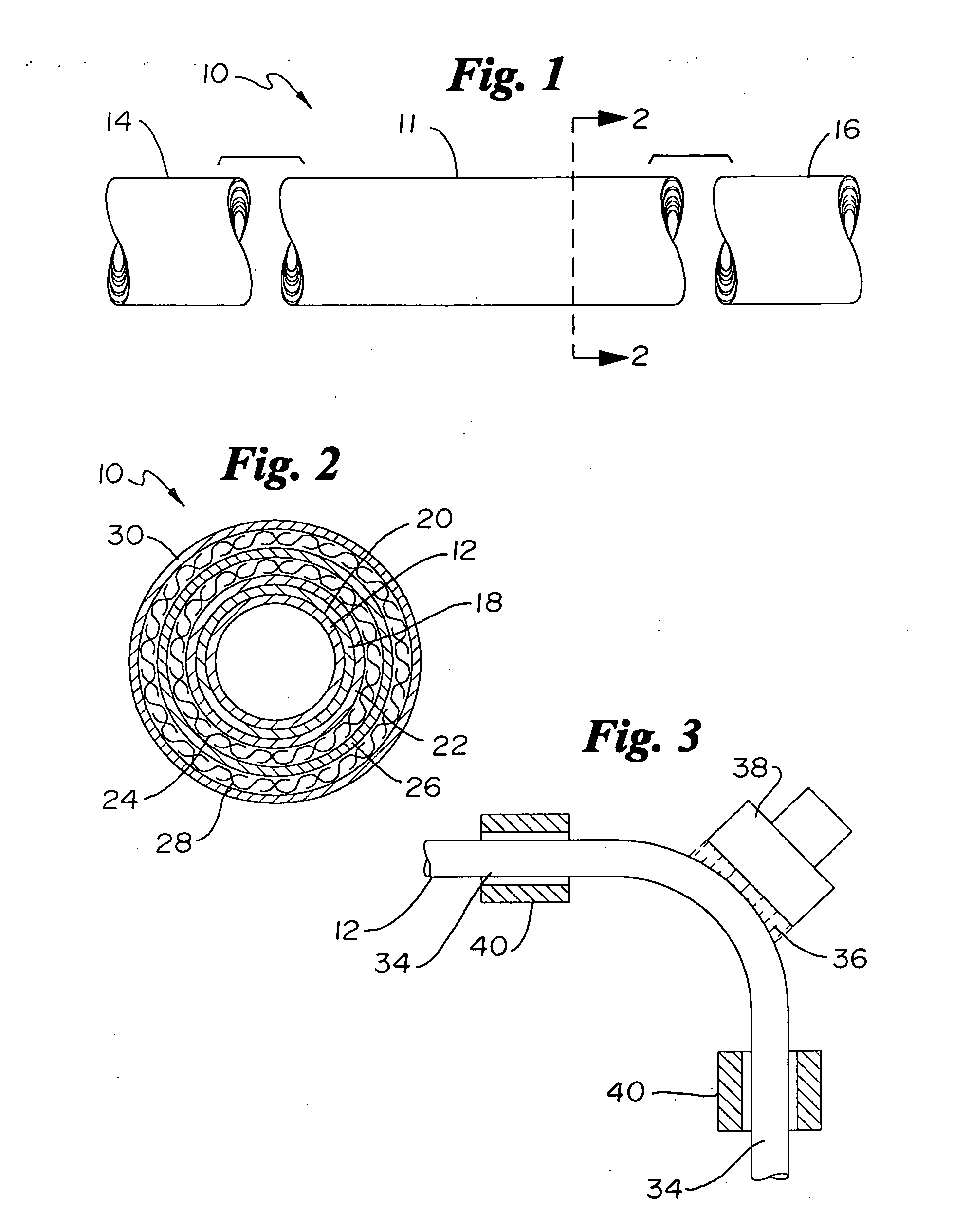
[0036] Referring now to the drawings wherein like reference numerals indicate like elements throughout the several views, FIG. 1 is a partial plan view of a portion of a catheter shaft incorporated into a polymer braid catheter according to a preferred embodiment. According to a preferred embodiment, a catheter shaft 10 comprises at least one elongate generally tubular member 11 having a proximal end 14 and a distal end 16 with at least one lumen therethrough.

[0037] In a preferred embodiment, catheter shaft 10 may comprise one or more components of different catheter types. These catheter types include, but are not limited to, a single-operator-exchange catheter, an over-the-wire catheter, a guide catheter, a diagnostic catheter, a balloon catheter, an angioplasty catheter, an atherectomy catheter, etc. A person of ordinary skill in the art would be familiar with different types of catheters appropriate for embodiments of the present invention. The need for and use of a catheter sh...


PUM

PropertyMeasurementUnit
stiffnessaaaaaaaaaa
flexibleaaaaaaaaaa
flexibilityaaaaaaaaaa

Abstract

The present invention relates generally to catheters for performing medical procedures including percutaneous transluminal coronary angioplasty. More particularly, the present invention relates to guide catheters, diagnostic catheters and balloon catheters with an improved shaft design. In a preferred embodiment, the present invention includes a catheter shaft comprising an elongate support member having an outer surface, the elongate support member preferably defining a lubricious liner; a first layer disposed over the lubricious liner, a second layer disposed over the first layer, a third layer disposed over the second layer, a fourth layer disposed over the third layer, and a fifth layer disposed over the fourth layer. In preferred embodiments, the first and third layers comprise an ultraviolet-curable epoxy which is cured to desired degrees at select axial locations on the shaft to provide desired stiffness.

Description

CROSS REFERENCE TO CO-PENDING APPLICATTIONS [0001] This application is a continuation of U.S. application Ser. No. 10 / 034,697, filed Dec. 27, 2001, the entire disclosure of which is incorporated herein by reference.FIELD OF THE INVENTION [0002] The present invention relates generally to catheters for performing medical procedures including intravascular diagnosis and treatment. More particularly, the present invention relates to catheters with an improved shaft design. BACKGROUND OF THE INVENTION [0003] The use of intravascular catheters has become an effective method for treating many types of vascular disease. In general, an intravascular catheter is inserted into the vascular system of the patient and navigated through the vasculature to a desired target site. Using this method, virtually any target site in the patient's vascular system may be accessed, including the coronary, cerebral, and peripheral vasculature. Examples of therapeutic procedures utilizing intravascular cathete...

Claims


Application Information

Patent Timeline
Patent Type & Authority Applications(United States)
IPC IPC(8): A61L29/08A61L29/10A61M25/00
CPCA61L29/085A61L29/106A61M25/0045Y10T428/139A61M25/0053A61M25/0054A61M25/005
Inventor PEPIN, HENRY J.
Owner BOSTON SCI SCIMED INC
Why Eureka
Try Eureka