Device for converting thermal energy

a technology of thermal energy and device, applied in the direction of indirect heat exchangers, compression machines, stationary tubular conduit assemblies, etc., can solve the problems of affecting the stability of the arrangement, affecting the operation safety, and advantageously slight losses in strength in the support body, so as to reduce or uniformly distribute the stresses in the profile body, the effect of improving the introduction of force in the axially remote heat exchanger

Active Publication Date: 2018-02-20
ECOP TECH
View PDF9 Cites 0 Cited by
  • Summary
  • Abstract
  • Description
  • Claims
  • Application Information

AI Technical Summary

Benefits of technology

[0020]In order to diminish or uniformly distribute the stresses in the profile body, it is advantageous to provide several outer elements, wherein preferably precisely two connecting bridges are provided between the inner element and each outer element. The connecting bridges are preferably arranged with the outer elements around the inner element in a star-shaped manner. In terms of force transmission, it is beneficial for the distance between the connecting bridges to continuously increase outwardly in a radial direction. Alternatively or additionally, the width of the connecting bridge can diminish outwardly in a radial direction.
[0021]To achieve an especially stable embodiment at a low material outlay, it is beneficial for the at least one outer element of the support body to be designed as a cylindrical receptacle for the outer heat exchanger. Alternatively, the receptacle can be inwardly partially open. Because the axially remote heat exchanger is not continuously supported, one core per heat exchanger can be omitted when casting. In addition, the introduction of force in the axially remote heat exchanger can be improved, making it possible to reduce the stresses emanating from centrifugal forces.
[0022]A preferred embodiment further provides that the support body comprises a cylindrical enclosure that surrounds the outer elements. The outer elements are here fastened to the interior side of the cylindrical enclosure. The cylindrical jacket tangibly reduces the frictional losses in the rotating operating state of the device. The rotor is preferably operated in a space with an ambient pressure of less than 50 mbar absolute pressure, in particular less than 5 mbar absolute pressure.

Problems solved by technology

In this embodiment, the heat exchangers can disadvantageously bend at the ends between the clamps during operation, thereby detracting from the stability of the arrangement.
In addition, operating safety can hereby not be ensured.
As a result, advantageously slight losses in strength arise in the support body, if any.

Method used


Image

  • Device for converting thermal energy
  • Device for converting thermal energy
  • Device for converting thermal energy

Examples


Embodiment Construction

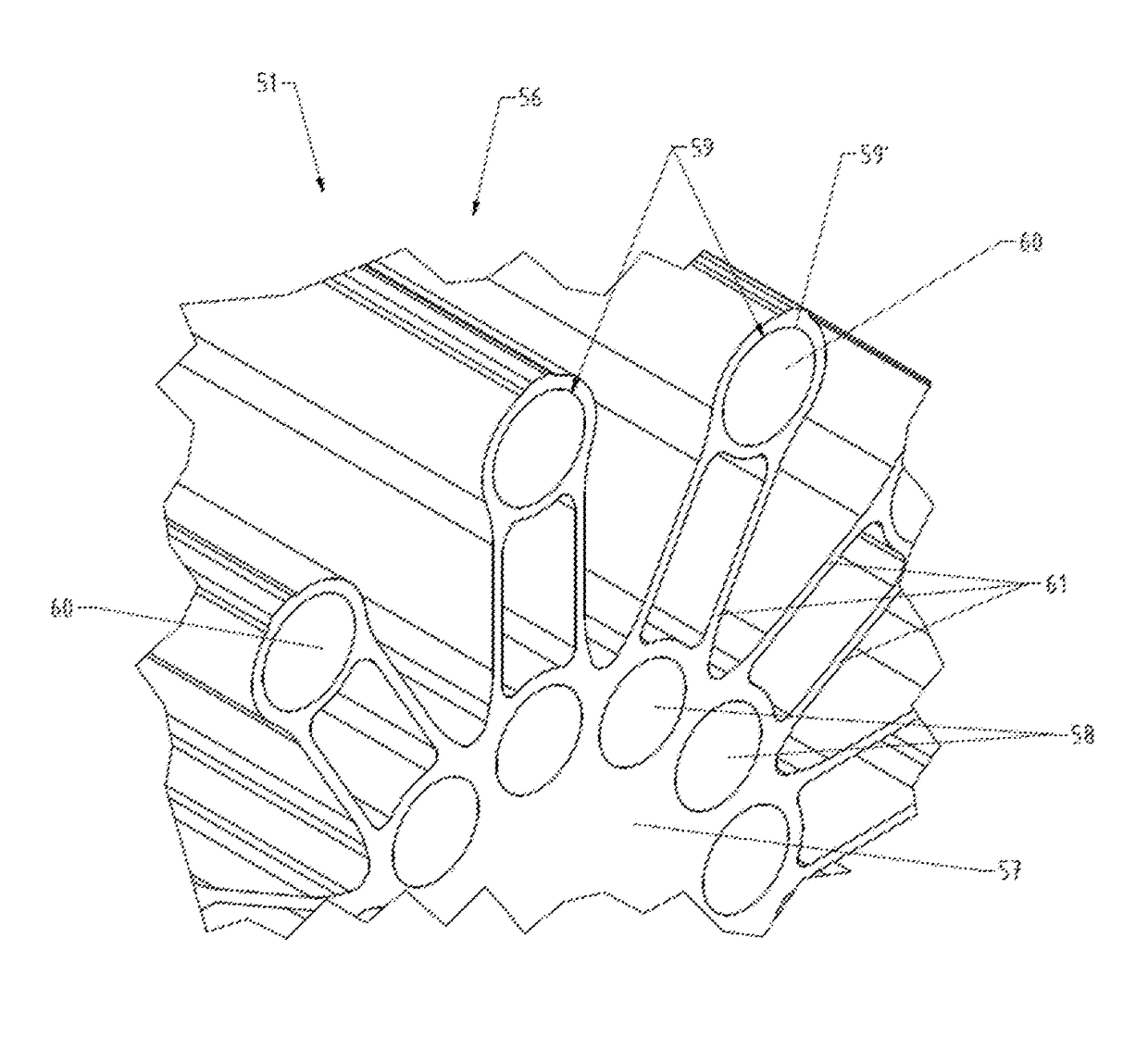
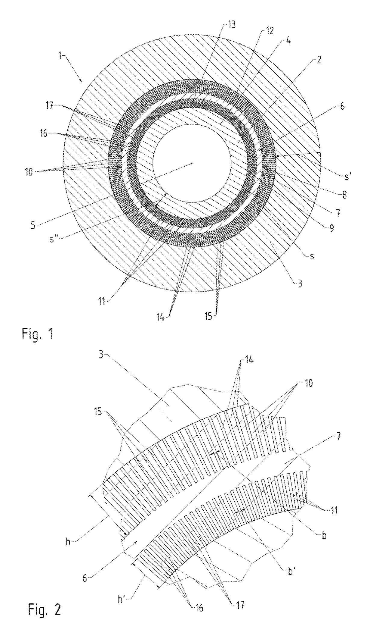
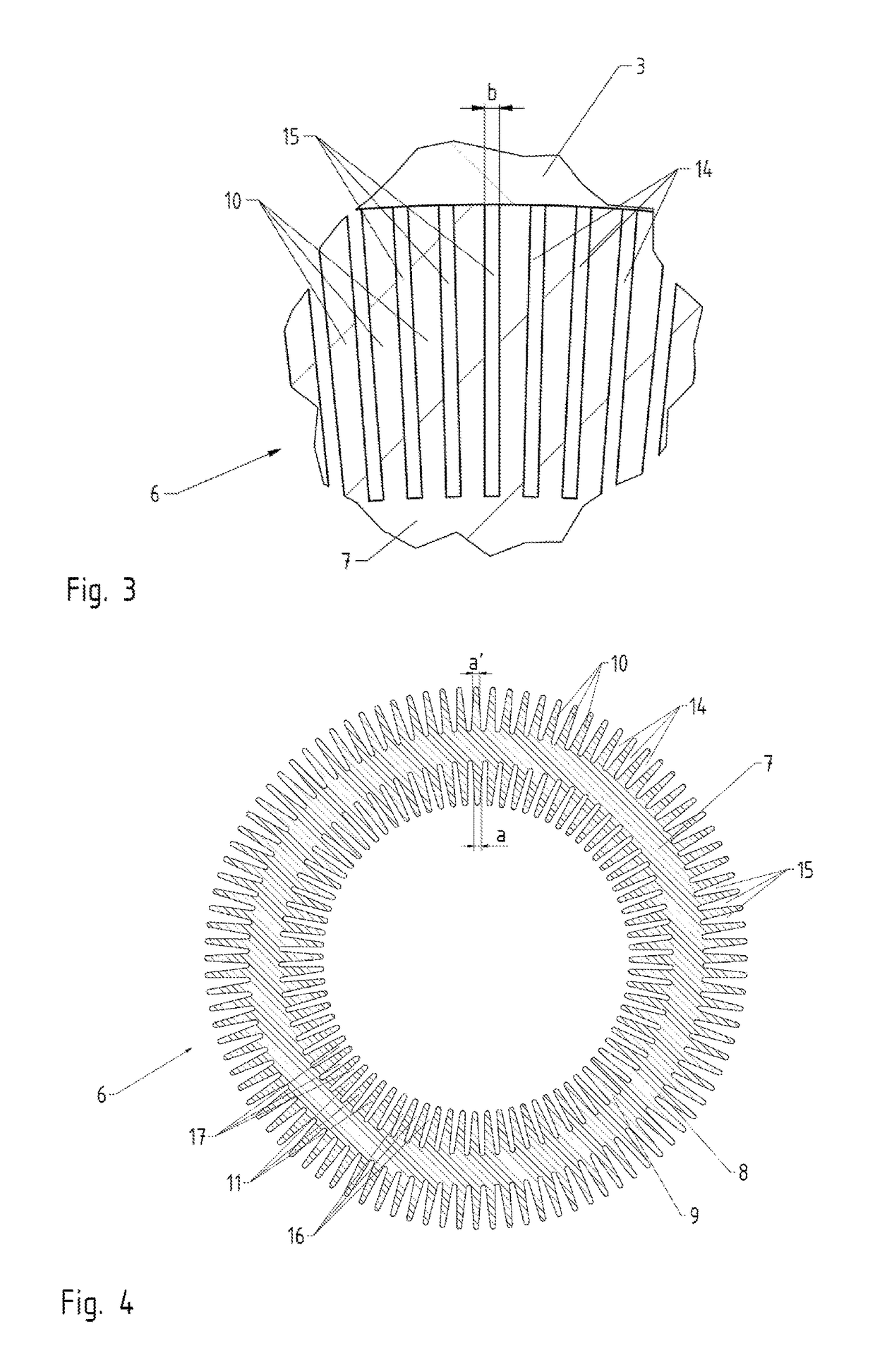
[0044]FIG. 1 shows a heat exchanger 1 to be installed in a rotating device 20 for converting thermal energy by means of mechanical energy and vice versa (see FIG. 7, 8). The heat exchanger 1 comprises an inner longitudinal element 2 and an outer pipe 3, which envelops the inner longitudinal element 2. A hollow inner pipe 4 is provided as the inner longitudinal element 2. The outer pipe 3 and inner pipe 4 are coaxially situated relative to a central longitudinal extension axis 5. Located between the inner pipe 4 and outer pipe 3 is a heat transmission pipe 6, which runs coaxially to the outer pipe 3 or inner pipe 4 in the longitudinal direction of the heat exchanger 1. The heat transmission pipe 6 comprises a wall 7 with an outer lateral surface 8 and an inner lateral surface 9, from which protrude outer lamellae 10 or inner lamellae 11. The lamellae 10, 11 extend in the direction of the longitudinal extension axis 5 of the heat transmission pipe 6. The outer lamellae 10 protrude fro...


PUM


Abstract

The invention relates to a device for converting thermal energy of a low temperature into thermal energy of a high temperature by means of mechanical energy, and vice versa, comprising a rotor which is mounted so as to rotate about a rotational axis and in which a flow channel is provided for a working medium that circulates in a closed circuit process, said medium being conducted outwards, relative to the rotational axis, in a compression unit in order to increase pressure, and being conducted inwards, relative to the rotational axis, in an expansion unit in order to reduce pressure. At least one heat exchanger is provided for exchanging heat between said working medium and a heat exchange medium.

Description

CROSS REFERENCE TO RELATED APPLICATIONS[0001]The present application is a U.S. National Phase of International Patent Application Serial No. PCT / AT2015 / 050005, entitled “DEVICE FOR CONVERTING THERMAL ENERGY,” filed on Jan. 8, 2015, which claims priority to Austrian Patent Application No. A50014 / 2014, entitled “DEVICE FOR CONVERTING THERMAL ENERGY,” filed on Jan. 9, 2014, the entire contents of each of which are hereby incorporated by reference for all purposes.TECHNICAL FIELD[0002]The invention relates to a device for converting thermal energy of a low temperature into thermal energy of a higher temperature by means of mechanical energy and vice versa with a rotor mounted so that it can rotate around a rotational axis, in which rotor is provided a flow channel for a working medium that passes through a closed cycle, which working medium is conducted essentially radially outward relative to the rotational axis in a compressor unit so as to increase the pressure and is constructed ess...

Claims


Application Information

Patent Timeline
Patent Type & Authority Patents(United States)
IPC IPC(8): F25B3/00F28D11/04
CPCF28D11/04F25B3/00F28D7/10
Inventor ADLER, BERNHARDRIEPL, SEBASTIAN
Owner ECOP TECH
Why Eureka
Try Eureka