Stiffness control for electroactive actuators

a technology of electroactive actuators and stiffness control, which is applied in the direction of piezoelectric/electrostrictive device details, device material selection, catheters, etc., can solve the problems of high stiffness control within eap actuators, and achieve the effect of improving the range of motion and force achievable in a single eap structur

Active Publication Date: 2019-11-14
KONINKLJIJKE PHILIPS NV
View PDF0 Cites 9 Cited by
  • Summary
  • Abstract
  • Description
  • Claims
  • Application Information

AI Technical Summary

Benefits of technology

[0027]It has been realised by the inventors that the range of motions and forces achievable in a single EAP structure may be improved in the case that a greater degree of control were possible over the stiffness

Problems solved by technology

Stiffness control within EAP actuators is presently highly limited in the state of the art, exten

Method used


Image

  • Stiffness control for electroactive actuators
  • Stiffness control for electroactive actuators
  • Stiffness control for electroactive actuators

Examples


Embodiment Construction

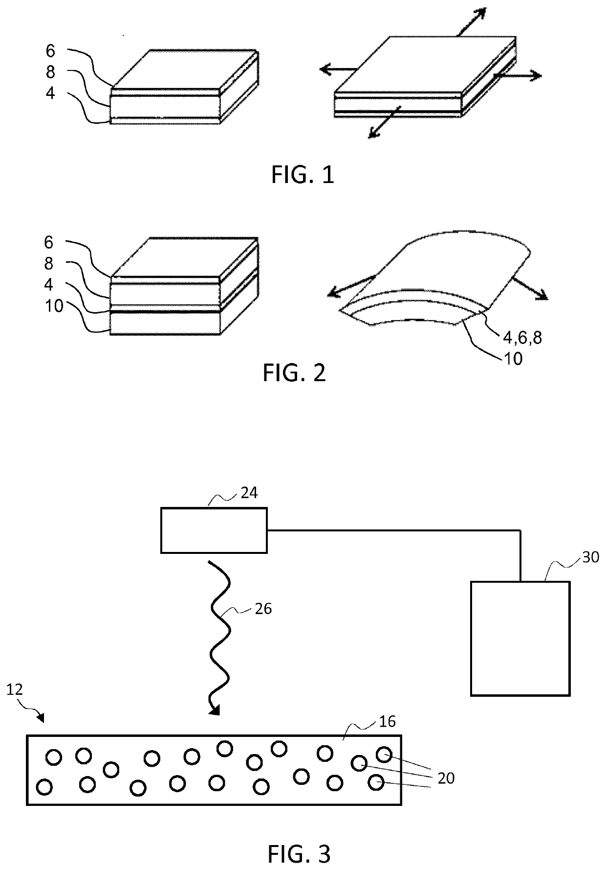
[0089]The invention provides an electroactive material actuator device having a controllable stiffness profile. An actuator member of the device comprises an electroactive material such as an electroactive polymer having light absorbing filler elements embedded or contained therein. The light absorbing filler elements are adapted to absorb and convert incident light energy to heat energy to therefore heat surrounding sections of the EAP material. By selectively controlling an intensity level or spectral composition of a light source directed at the actuator member, a specific degree and spread of heating can be achieved across the member and, as a result, a specific desired stiffness or flexibility profile realised across the body of the actuator member.

[0090]FIG. 3 schematically illustrates a simple first example of an actuator device in accordance with one or more embodiments of the invention. The actuator device comprises an actuator member 12 being formed of an electroactive pol...


PUM


Abstract

An actuator device is provided having a controllable stiffness profile, wherein an actuator member (12) comprises an electroactive polymer material (16) having light absorbing filler elements (20) embedded therein. The filler elements are adapted to absorb and convert incident light (26) to heat energy to therefore heat surrounding sections of the electroactive material. By selectively controlling an intensity level or spectral composition of a light source (24) directed at the actuator member, a specific degree and spread of heating can be achieved across the member and, as a result, a specific desired stiffness or flexibility profile can be realised across the actuator member.

Description

FIELD OF THE INVENTION[0001]This invention relates to an actuator device having controllable stiffness and in particular to an electroactive material based actuator member having controllable stiffness.BACKGROUND OF THE INVENTION[0002]Electroactive materials (EAMs), and in particular electroactive polymers (EAPs) are an emerging class of materials within the field of electrically responsive materials. EAPs can work as sensors or actuators and can easily be manufactured into various shapes allowing easy integration into a large variety of systems.[0003]Materials have been developed with characteristics such as actuation stress and strain which have improved significantly over the last ten years. Technology risks have been reduced to acceptable levels for product development so that EAPs are commercially and technically becoming of increasing interest. Advantages of EAPs include low power, small form factor, flexibility, noiseless operation, accuracy, the possibility of high resolutio...

Claims


Application Information

Patent Timeline
IPC IPC(8): H01L41/09H01L41/18H01L41/04A61M25/01F03G7/00
CPCH01L41/042H01L41/0926A61M25/0158A61M2025/09175A61M2025/0058H01L41/183F03G7/005A61M2025/09133H10N30/802H10N30/204H10N30/852
Inventor PELSSERS, EDUARD GERARD MARIEHENDRIKS, PETRUS CORNELISHAKKENS, FRANCISCUS JOHANNES GERARDUSHILGERS, ACHIMVAN DEN ENDE, DAAN ANTONJOHNSON, MARK THOMAS
Owner KONINKLJIJKE PHILIPS NV
Why Eureka
Try Eureka