Sliding device used on the supporting shaft
- Summary
- Abstract
- Description
- Claims
- Application Information
AI Technical Summary
Benefits of technology
Problems solved by technology
Method used
Image
Examples
embodiment 1
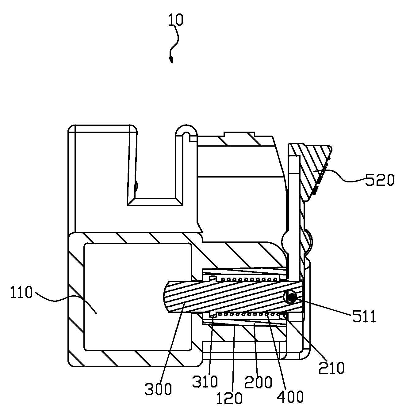
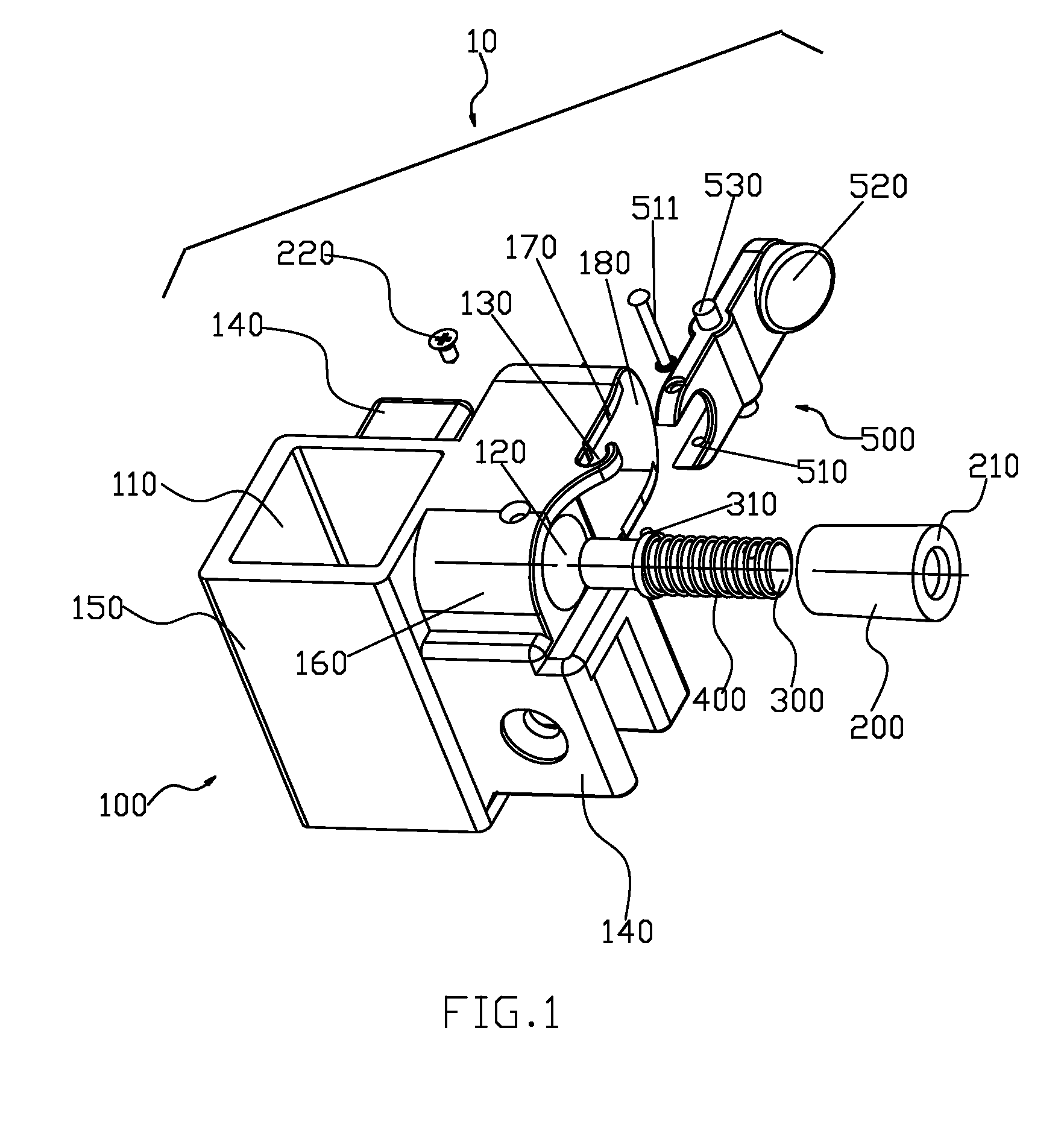
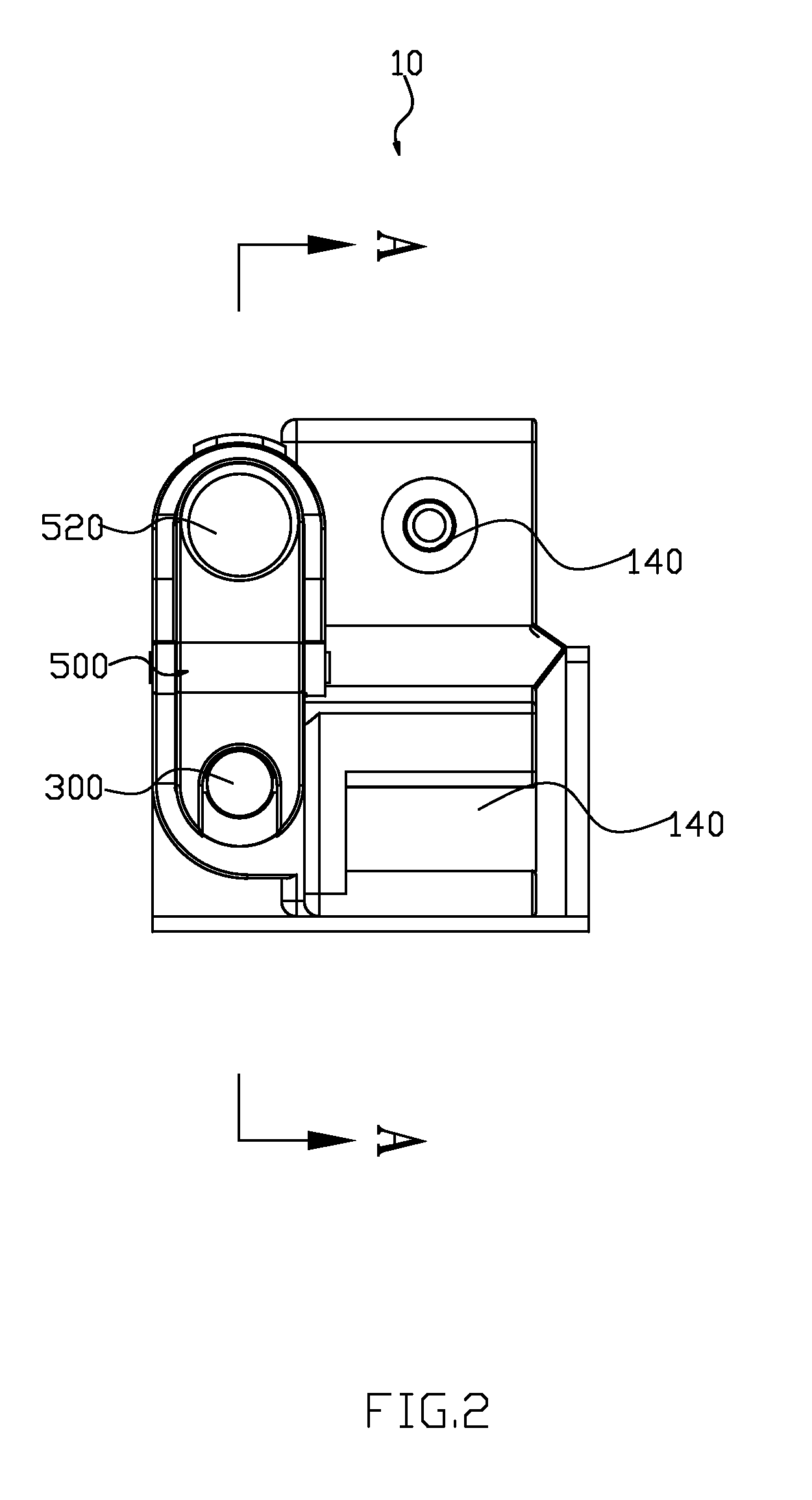
[0033]Referring to FIGS. 1 to 4, the sliding device 10 comprises a sliding base 100, an orientation sleeve 200, a bolt 300, an elastic body 400 and a button 500.
[0034]The sliding base 100 comprises a sliding through hole 110 through upside and downside, a main sleeve 150 encircling the sliding through hole 110, a horizontal mounting hole 120 through inside and outside, a side sleeve 160 encircling the mounting hole 120 and fixed to a side of the main sleeve 150, at least two connecting parts 140 that are fixed to the outside of the main sleeve 150 and are used to being connected to the forficiform connecting rod, two disjunct basal walls 170 that are fixed to sides of the main sleeve 150 and beside the side sleeve 160, and a back wall 180 that is fixed to the two basal walls 170. Wherein the sliding through hole 110 is fittingly covered on the supporting shaft slidably to make the sliding base 100 and the supporting shaft form a sliding connection up and down. The mounting hole 120 ...
embodiment 2
[0043]Referring to FIG. 5, the mounting slot 130 has an upward mouth. The pull part 510 is a ring, which covers the outer end part that the bolt 300 protrudes outside of the ringed lid 210, and there is a rivet 511 to get through the pull part 510 and the outer end part.
embodiment 3
[0044]Referring to FIGS. 6 and 7,the present embodiment has differences with the embodiment 1 as follows: Installation modes of the button 500 and the sliding base 100 are different. The upside of the sliding base 100 has a mounting slot 190 that the button 500 can get through. The mounting slot 190 has a raised platform 191. The clearance of the mounting slot 190 is bigger than the thickness of the button 500 to make the button 500 and the sliding base 100 form an active connection with relative turn and relative slide synchronously.
[0045]In normal state, the bolt 300 is at a first position at the effect of the spring 400; here the bolt 300 is inserted into the locking hole of the supporting shaft to be fixed to the first position. When the bolt 300 is needed to be withdrew, the button 500 is pressed, and the pull part of the button pulls the button 300 upwards utilizing a pivot namely the raised platform 191 of the mounting slot 190 to make the bolt 300 being positioned to a secon...
PUM
 Abstract
Description
Claims
Application Information
 - R&D
- Intellectual Property
- Life Sciences
- Materials
- Tech Scout
- Unparalleled Data Quality
- Higher Quality Content
- 60% Fewer Hallucinations
Browse by: Latest US Patents, China's latest patents, Technical Efficacy Thesaurus, Application Domain, Technology Topic, Popular Technical Reports.
© 2025 PatSnap. All rights reserved.Legal|Privacy policy|Modern Slavery Act Transparency Statement|Sitemap|About US| Contact US: help@patsnap.com


