Blood pressure meter

a blood pressure meter and meter technology, applied in the field of blood pressure meter, can solve the problem of relative large space around the inlet pipe, and achieve the effect of further promotion of the product and promotion of the product miniaturization

Active Publication Date: 2019-11-19
OMRON HEALTHCARE CO LTD
View PDF18 Cites 0 Cited by
  • Summary
  • Abstract
  • Description
  • Claims
  • Application Information

AI Technical Summary

Benefits of technology

[0006]However, with the blood pressure meters disclosed in Patent Document 1 (JP H09-101220A) and Patent Document 2 (JP 2013-220187A), there is a relatively large space around the inlet pipe (or the fluid path) in which a component is not disposed. Accordingly, there is a possibility that miniaturization of a product, in particular, miniaturization in a planar direction can be further promoted by effectively using the space.
[0007]Thus, one or more embodiments of the present invention provide a blood pressure meter that can promote miniaturization of a product, in particular, miniaturization in a planar direction.

Problems solved by technology

However, with the blood pressure meters disclosed in Patent Document 1 (JP H09-101220A) and Patent Document 2 (JP 2013-220187A), there is a relatively large space around the inlet pipe (or the fluid path) in which a component is not disposed.

Method used


Image

  • Blood pressure meter
  • Blood pressure meter
  • Blood pressure meter

Examples


Embodiment Construction

[0063]Hereinafter, an embodiment of the present invention will be described in detail with reference to the drawings. In the embodiment given below, the same constituent elements are given the same reference numerals and a description thereof is omitted.

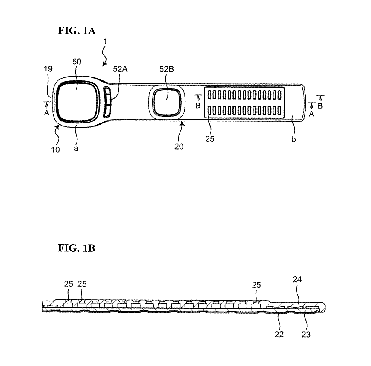
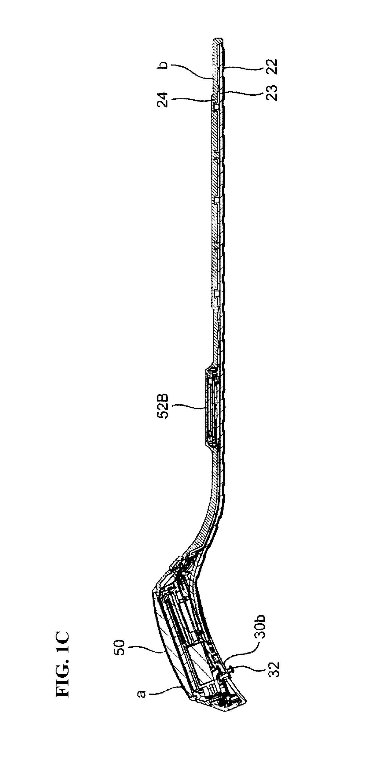
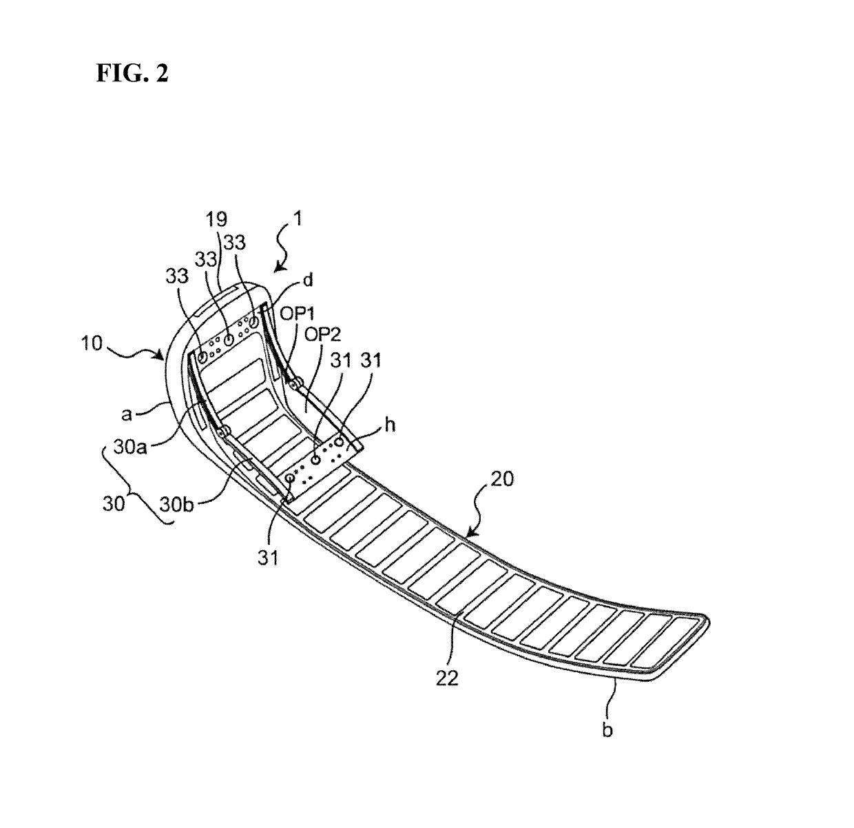
[0064]FIG. 1A is a top view showing an external appearance of a blood pressure meter 1 according to an embodiment of the present invention. FIG. 1B is a vertical cross-sectional view of the blood pressure meter 1 taken along the line B-B shown in FIG. 1A. FIG. 1C is a vertical cross-sectional view of the blood pressure meter 1 taken along the line A-A shown in FIG. 1A. FIG. 2 is a bottom view of the blood pressure meter 1 shown in FIG. 1. FIG. 3 is a perspective view of the blood pressure meter 1 shown in FIG. 1 when the blood pressure meter 1 is worn wrapped around a measurement area. FIG. 4 is a diagram illustrating the blood pressure meter 1 shown in FIG. 3 as viewed from a direction vertical to the loop of the belt. FIG. 5 is an ...


PUM


Abstract

A blood pressure meter includes a pump and a first fluid path provided inside a main body. The first fluid path feeds a fluid from the pump to a fluid bladder or discharges the fluid from the fluid bladder. A pressure sensor is mounted on a first substrate disposed inside the main body. A second fluid path that introduces the fluid from the fluid bladder to the pressure sensor is provided. The second fluid path includes an inlet pipe that is integrally formed with a sensor package that incorporates the pressure sensor, and extends straight between the fluid bladder and the pressure sensor. A second substrate on which a blood pressure measurement element is mounted is disposed in a space that is located between the first substrate and the fluid bladder in a thickness direction and is adjacent to the second fluid path in a planar direction.

Description

TECHNICAL FIELD[0001]The present invention relates to a blood pressure meter. More specifically, the invention relates to an electronic blood pressure meter that detects the pressure of a fluid supplied to a blood pressure measurement cuff by using a pressure sensor through an inlet pipe that is in communication with the cuff and obtains a blood pressure value based on the detected pressure.BACKGROUND ART[0002]As this type of blood pressure meter, for example, a blood pressure meter as disclosed in Patent Document 1 (JP H09-101220A) is known that includes a pressure sensor module including a tubular inlet pipe integrally formed on a bottom surface of a package incorporating a pressure sensor so as to protrude from the bottom surface. The pressure sensor module package is attached onto an upper surface of a circuit substrate, with the inlet pipe extending down to the circuit substrate through a through hole formed in advance in the circuit substrate. The inlet pipe is connected to a ...

Claims


Application Information

Patent Timeline
Patent Type & Authority Patents(United States)
IPC IPC(8): A61B5/02A61B5/022A61B5/00A61B5/023
CPCA61B5/681A61B5/023A61B5/742A61B5/02233A61B5/022A61B2560/0214
Inventor ONO, KENJIADACHI, YUMATOKKO, YOSHIHIDEYAMAZAKI, EISUKE
Owner OMRON HEALTHCARE CO LTD
Why Eureka
Try Eureka