Wheel frame component

a technology of wheel frame and component, which is applied in the direction of wheel frame, vehicle components, transportation and packaging, etc., can solve the problems of high cost of prior art multiple directional wheel frame manufacturing, insufficient ride quality, and prior attempts that do not excel, so as to reduce fatigue and mechanical failure risks.

Active Publication Date: 2019-11-19
ROTACASTER WHEEL
View PDF142 Cites 1 Cited by
  • Summary
  • Abstract
  • Description
  • Claims
  • Application Information

AI Technical Summary

Benefits of technology

[0033]Alternatively, where a soft roller material is required for greater traction or quieter ride properties, the rollers may be over-molded as described in the Applicant's published patent application No. WO2011047443, the disclosure of which is hereby incorporated herein in its entirety by this reference. Over-molding of the rollers may be performed over axles of a harder and more rigid material suitable for forming a structural component, such as acetal. In any case, although forming the wheel from one or more metal components is within the scope of the disclosure, where the rollers and frame are made from polymeric materials, then preferably, the components, such as axles constituting or being engaged with relative moving parts, are made from materials other than metals to minimize relative abrasion and early onset of wear- and tear-related performance failures.
[0041]Advantageously, a single-piece molded roller core incorporating the axle pins / heads may be used. Alternatively, the roller may comprise a full solid piece roller. In another alternative, a roller undersized in diameter may be used, which can be over-molded with selected materials adapted for improved wear and tear resistance, non-marking or improved traction, etc., or other desirable roller ground-engaging properties.
[0043]Each head, when viewed from a side in the line of the main axis, may comprise a substantially triangular body comprising recesses on either of its isosceles angled sides to receive roller axle pins extending from the rollers. Each head may be completed upon assembly of the component parts of the wheel frame. The head may include an outer peripheral engagement means to further secure the engagement of the component wheel frame parts.
[0045]During assembly, the rollers may be press fitted into their respective opposed and spaced support head mounts so adjacent radial heads assist in retaining the roller during assembly.
[0048]Advantageously, the spigots are preferably short stubs of a constant cross-section or constantly graded cross-section. The spigots may, therefore, not include a stepped shaft profile. Preferably, the entire length of the spigot provides an engagement surface in the corresponding receiving bore of the recess for a non-releasable friction fit. Preferably, the recess is a blind hole to minimize fatigue and mechanical failure risks in small-frame components and for aesthetic reasons. However, in large wheel frames where the recess is formed in a greater body of material, through-holes may be desirable for the recesses as described above.
[0051]Accordingly, the linear structure of the hub rim, the beam and the spigot in series is very strong. In its preferred form, it provides a strong and rigid inner structure of the hub rim of the wheel frame. When the wheel is coupled to the drive means, the drive means is preferably engaged through the strongest part of the wheel frame for the most efficient and effective transfer of power to the wheel. The beam is sufficiently long to extend axially parallel radially inwardly relative to a corresponding roller. The length of each beam allows space for a member of the second plurality of peripheral roller supporting arms to extend radially outwardly within the wheel's and the assembled wheel frame's side profile. Each member of the second plurality of peripheral roller supporting arms comprises a radial shaft with a wide base at the inner base tapering radially outwardly to a peripheral roller supporting head. The head preferably faces in the same direction as the offset and diagonally adjacent heads of the first plurality of peripheral roller supporting arms.

Problems solved by technology

The cost of manufacture of prior art multiple directional wheel frames is high, both in terms of time and materials.
Inadequate ride quality is another factor in which prior attempts do not excel.
Also, prior art attempts suffer from poor roller axle housing fit and impact resistance.
These result in substantial wear and deterioration of the wheel and its performance: loosening axle mounts and impact damage discourage use of multiple applications where there is a low tolerance to mechanical failure or deterioration in performance.
Furthermore, prior attempts tend to use metal components, such as axles, in engagement with moving components made of softer or weaker materials, thereby increasing cost and the likelihood of mechanical failure or accelerated wear and tear.

Method used


Image

  • Wheel frame component
  • Wheel frame component
  • Wheel frame component

Examples


Embodiment Construction

[0064]Preferred features of this disclosure will now be described with particular reference to the accompanying drawings. However, it is to be understood that the features illustrated in and described with reference to the drawings are not to be construed as limiting on the scope of the invention.

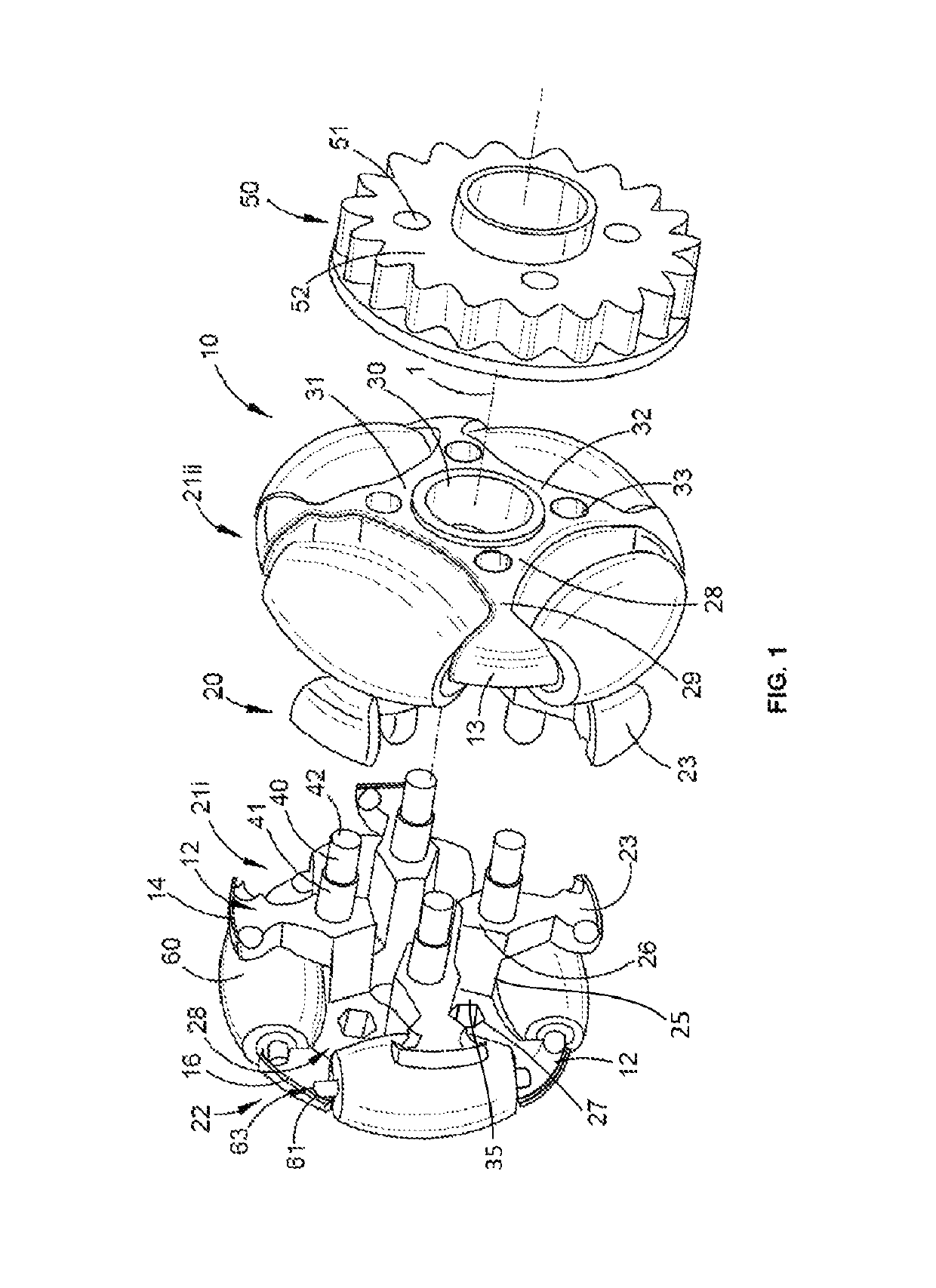
[0065]Referring to FIG. 1, there is shown a multiple directional wheel 10 including a wheel frame 20 comprising identical component parts 21i and 21ii. Each of the wheel frame components 21i and 21ii comprise: a hub 30 having a main axis 1 about which the multiple directional wheel 10 is adapted to rotate; a hub rim 31 radially surrounding the hub 30; a first plurality (four shown) of peripheral roller supporting arms (“first arms”) 22 radially extending from the hub rim 31 and aligned in a first plane; and a second plurality of peripheral roller supporting arms (“second arms”) 23, each member arm of the second plurality of peripheral roller supporting arms having a radially inner base 26 a...


PUM


Abstract

A multiple directional wheel including a wheel frame comprising identical component parts. Each of the wheel frame components comprise: a hub having a main axis about which the multiple directional wheel is adapted to rotate; a hub rim radially surrounding the hub; a first plurality of peripheral roller supporting arms (“first arms”) radially extending from the hub rim and aligned in a first plane; and a second plurality of peripheral roller supporting arms, each member arm of the second plurality of peripheral roller supporting arms having a radially inner base and being circumferentially offset with respect to diagonally adjacent members of the first plurality of peripheral roller supporting arms. Each of the wheel frame components further comprise a plurality of beams corresponding to the number of member arms of the second plurality of peripheral roller supporting arms, each respective beam extending from the hub rim to a corresponding inner base of a member arm of the second plurality of peripheral roller supporting arms, and a plurality of spigots extending from each corresponding one of the plurality of beams or the inner bases. The second plurality of peripheral roller supporting arms lie in a second plane normal to the main axis, spaced from, and parallel to, the first plane; and each of the spigots from one of the wheel frame components is received in a recess formed in a facing surface of a complementary one of the wheel frame components to join the wheel frame components to form the wheel frame.

Description

CROSS-REFERENCE TO RELATED APPLICATIONS[0001]This application is a national phase entry under 35 U.S.C. § 371 of International Patent Application PCT / AU2016 / 000001, filed Jan. 6, 2016 designating the United States of America and published in English as International Patent Publication WO 2016 / 109867 A1 on Jul. 14, 2016, which claims the benefit under Article 8 of the Patent Cooperation Treaty to Australian Patent Application Serial No. 2015900018, filed Jan. 6, 2015.TECHNICAL FIELD[0002]This application relates to a wheel frame component. More particularly, this application relates to a wheel frame component forming part of a multiple directional wheel.BACKGROUND[0003]The following references to and descriptions of prior proposals or products are not intended to be, and are not to be construed as, statements or admissions of common general knowledge in the art. In particular, the following prior art discussion does not relate to what is commonly or well known by the person skilled i...

Claims


Application Information

Patent Timeline
Patent Type & Authority Patents(United States)
IPC IPC(8): B60B19/00B60B19/12
CPCB60B19/12B60B19/003B60B2900/325B60B2900/321B60B2900/112B60B2900/551B60B2900/351
Inventor MCKINNON, PETER R.
Owner ROTACASTER WHEEL
Why Eureka
Try Eureka