Camshaft adjusting device

a technology of adjusting device and camshaft, which is applied in the direction of mechanical equipment, machine/engine, engine components, etc., can solve the problems of complex disassembly and non-functional corresponding unused threads, and achieve the effect of flexibility

Active Publication Date: 2019-11-19
SCHAEFFLER TECH AG & CO KG
View PDF10 Cites 0 Cited by
  • Summary
  • Abstract
  • Description
  • Claims
  • Application Information

AI Technical Summary

Benefits of technology

[0010]The object of the invention is to provide a camshaft adjusting device that enables especially simple assembly of the camshaft adjuster with a camshaft.
[0012]In this way it is achieved that an integrally formed camshaft end or an integrally formed connection location for a camshaft adjuster is suitable both for a first hydraulic camshaft adjuster and also for a second hydraulic camshaft adjuster and an incorrect assembly of a camshaft adjuster on a camshaft not provided for this is avoided.
[0013]For a first hydraulic camshaft adjuster, for operating a central magnet for a central valve and for a second hydraulic camshaft adjuster, a decentralized control valve is provided. An incorrect assembly of a camshaft adjuster on an incorrect camshaft end would also have the effect that an incorrect oil interface would then be opposite the incorrectly installed camshaft adjuster. The result is complicated disassembly. This result is avoided according to the invention. A construction according to the invention also advantageously provides that the connection location for two hydraulic camshaft adjusters preferably controlled in different ways has the same construction.
[0017]The arrangement according to the invention achieves flexibility for the assembly of a camshaft adjuster with a certain function on one or more camshafts.

Problems solved by technology

An incorrect assembly of a camshaft adjuster on an incorrect camshaft end would also have the effect that an incorrect oil interface would then be opposite the incorrectly installed camshaft adjuster.
The result is complicated disassembly.
If a camshaft adjuster provided for the corresponding intake or exhaust camshaft is mounted accordingly, then the corresponding unused thread remains non-functional.

Method used


Image

  • Camshaft adjusting device
  • Camshaft adjusting device

Examples


Embodiment Construction

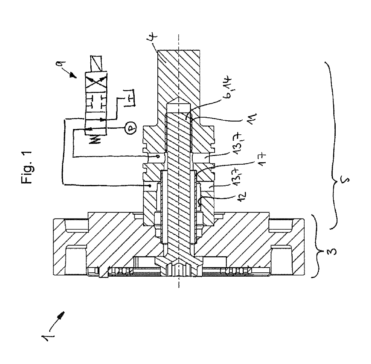
[0022]FIG. 1 shows a camshaft adjusting device 1 with a hydraulic camshaft adjuster 3 and with an integrally formed camshaft end 5.

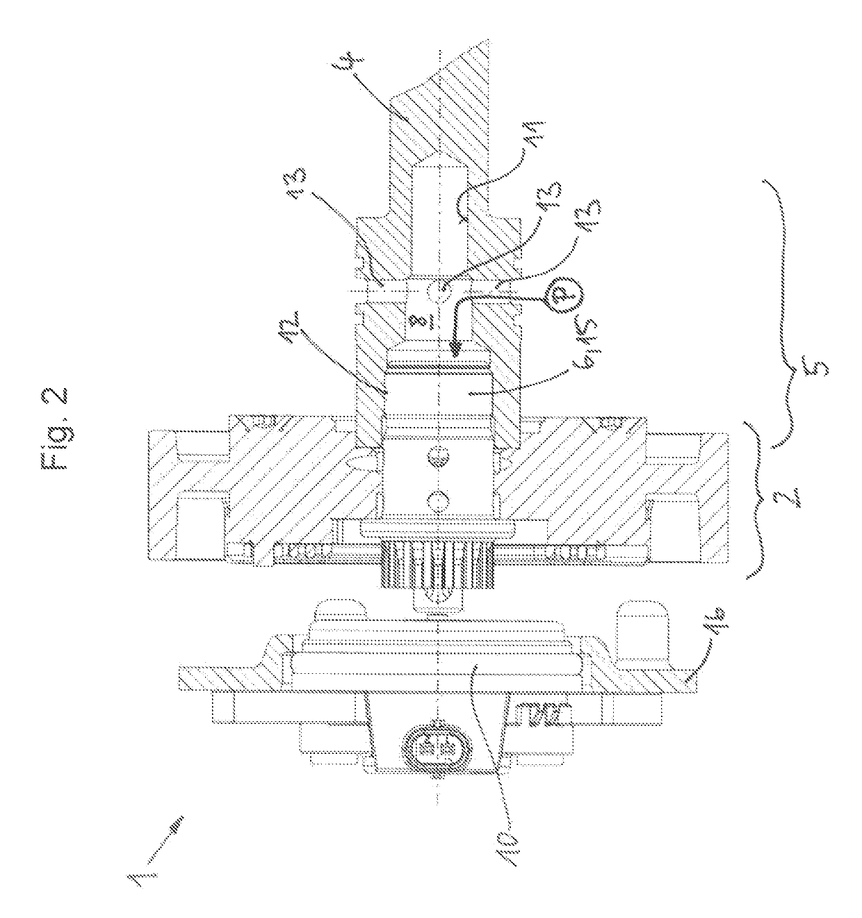
[0023]FIG. 2 shows a camshaft adjusting device 1 with another hydraulic camshaft adjuster 2 and with the integrally formed camshaft end 5 according to FIG. 1.

[0024]The difference between the camshaft adjusting device 1 in FIG. 1 and in FIG. 2 is that a first hydraulic or a second hydraulic camshaft adjuster 2, 3 is fastened to the camshaft end 5 of the camshaft 4. The camshaft end 4 is formed identically according to the invention in both embodiments and has two threads 11, 12 that are different from each other and in which the fastener formed as screw 6 engages. The screw 6 is formed for the second hydraulic camshaft adjuster 3 as a simple central screw 14. For the first hydraulic camshaft adjuster 2, the screw 6 is provided with a valve function—that is, a central valve screw 15. The central valve screw 15 and the central screw 14 engage in the respect...


PUM


Abstract

A camshaft adjusting device (1) is provided having a camshaft adjuster (2, 3) and a camshaft (4) characterized in that the camshaft (4) include a camshaft end (5) which is designed to receive a first hydraulically actuatable camshaft adjuster (2) as well to receive a second hydraulically actuatable camshaft adjuster (3).

Description

FIELD OF THE INVENTION[0001]The invention relates to a camshaft adjusting device.BACKGROUND OF THE INVENTION[0002]Camshaft adjusters are used in internal combustion engines to vary the control times of the combustion chamber valves, in order to variably shape the phase relation between a crankshaft and a camshaft in a defined angle range between a maximum advanced position and a maximum retarded position. Adapting the control times to the current load and rotational speed reduces the fuel consumption and emissions. For this purpose, camshaft adjusters are integrated into a drivetrain by which torque is transferred from the crankshaft to the camshaft. This drivetrain can be constructed, for example, as a belt, chain, or gearwheel drive.[0003]In a hydraulic camshaft adjuster, the driven element and the drive element form one or more pairs of mutually interacting pressure chambers that can be loaded with hydraulic medium. The drive element and the driven element are in a coaxial arrang...

Claims


Application Information

Patent Timeline
Patent Type & Authority Patents(United States)
IPC IPC(8): F01L1/34F01L1/344F01L1/352F01L1/047F01L1/24
CPCF01L1/24F01L1/047F01L1/344F01L1/352F01L1/3442F01L2001/34433F01L2001/2444F01L2001/0473
Inventor BAYRAKDAR, ALI
Owner SCHAEFFLER TECH AG & CO KG
Why Eureka
Try Eureka