
Heat pump system for vehicle

a heat pump and vehicle technology, applied in vehicle heating/cooling devices, vehicle components, transportation and packaging, etc., can solve the problems of increasing the size and weight of the cooling module disposed at the front of the vehicle, the complicated layout of the connection pipes supplying the refrigerant or the coolant to each of the heat pump systems, and the battery cooling system in the engine compartment becomes complicated, so as to simplify the heat pump system and simplify the layout of the connection pipes. , the effect of improving the heating efficiency

Active Publication Date: 2019-11-26
HYUNDAI MOTOR CO LTD +1
View PDF38 Cites 9 Cited by
  • Summary
  • Abstract
  • Description
  • Claims
  • Application Information

AI Technical Summary

Benefits of technology

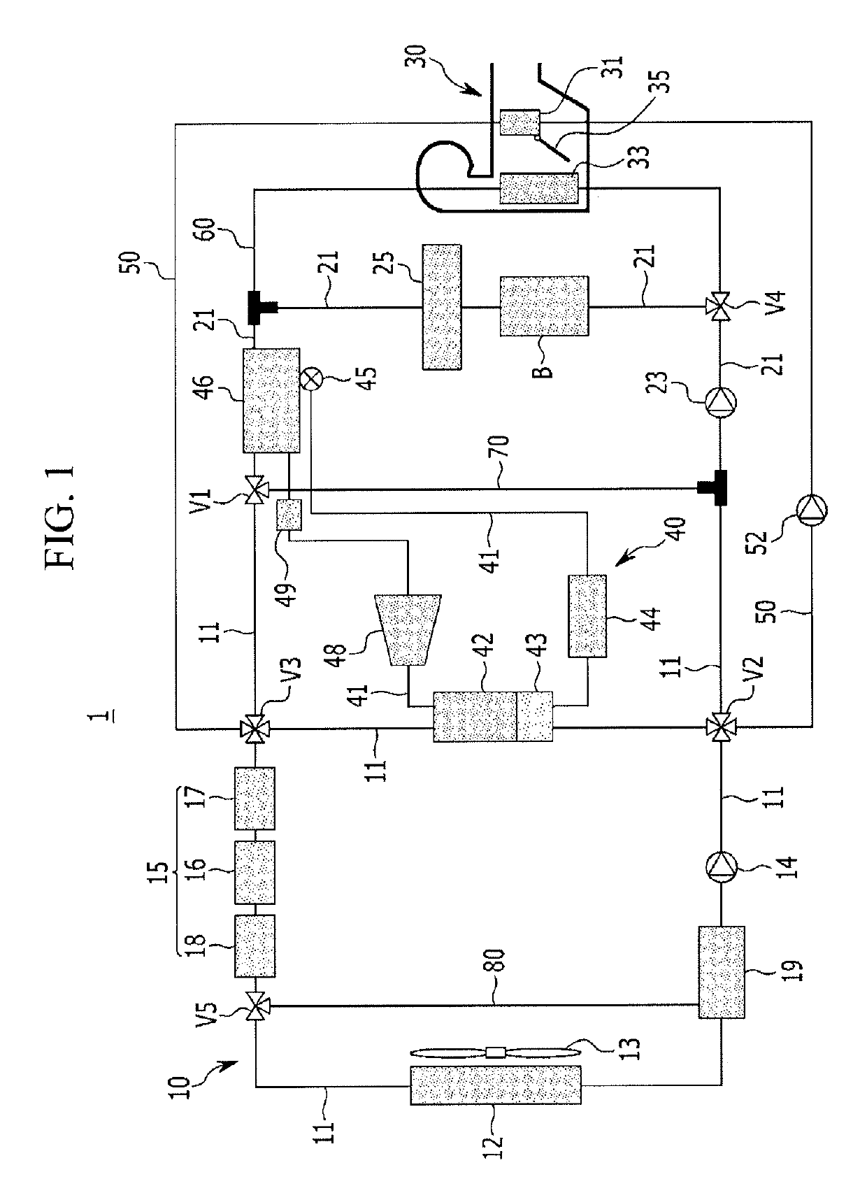
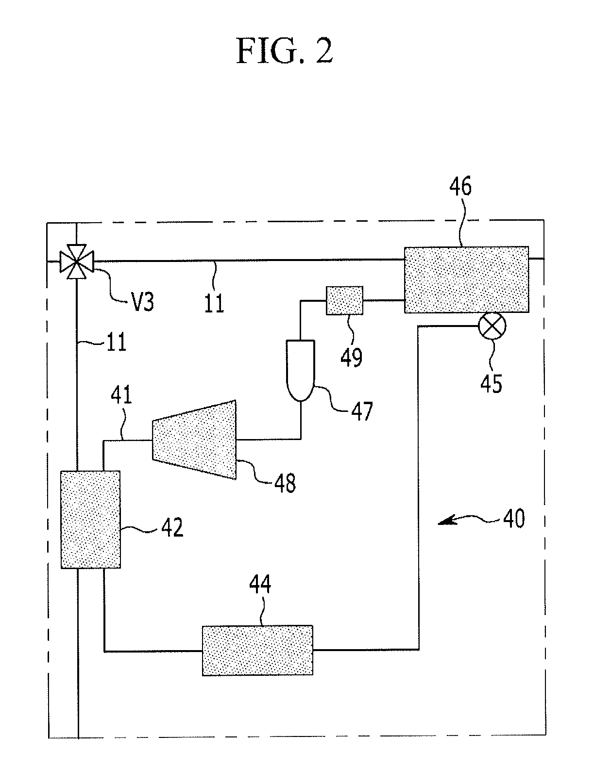
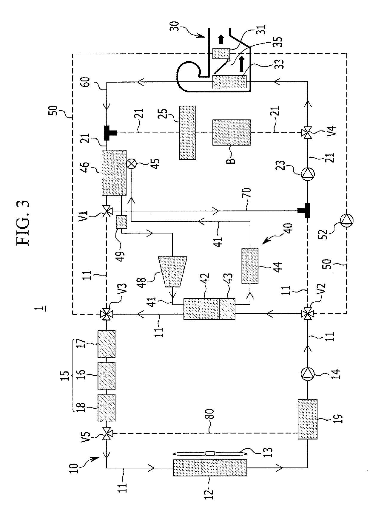
[0016]Various aspects of the present invention are directed to providing a heat pump system for a vehicle having the advantages of selectively exchanging thermal energy generated from a refrigerant at the time of condensing and evaporating the refrigerant with heat of a coolant, and controlling an internal temperature of the vehicle using a low-temperature coolant or a high-temperature coolant of which the heat is exchanged.
[0017]Further, various aspects of the present invention are directed to providing a heat pump system for a vehicle having advantages of improving the heating efficiency of the vehicle using waste heat of an electric component and a battery module, and increasing an entire travel distance of the vehicle by efficiently controlling a temperature of the battery module so that the battery module exhibits optimal performance.

Problems solved by technology

Therefore, a size and a weight of a cooling module disposed at the front of the vehicle are increased, and a layout of connection pipes supplying a refrigerant or a coolant to each of the heat pump system, the cooling device, and the battery cooling system in an engine compartment becomes complicated.

Method used


Image

  • Heat pump system for vehicle
  • Heat pump system for vehicle
  • Heat pump system for vehicle

Examples


Embodiment Construction

[0054]Reference will now be made in detail to various embodiments of the present invention(s), examples of which are illustrated in the accompanying drawings and described below. While the invention(s) will be described in conjunction with exemplary embodiments, it will be understood that the present description is not intended to limit the invention(s) to those exemplary embodiments. On the contrary, the invention(s) is intended to cover not only the exemplary embodiments, but also various alternatives, modifications, equivalents and other embodiments, which may be included within the spirt and scope of the invention as defined by the appended claims.

[0055]In addition, throughout the present specification, unless explicitly described to the contrary, the word “comprise” and variations such as “comprises” or “comprising”, will be understood to imply the inclusion of stated elements but not the exclusion of any other elements.

[0056]In addition, the terms “˜unit”, “˜means”, “˜part”, “...


PUM


Abstract

A heat pump system for a vehicle may include a cooling device including a radiator connected to a cooling line and a first water pump to cool an electric component; a battery module provided on a battery cooling line selectively connectable to the cooling line through a first valve; a heating, ventilation, and air conditioning (HVAC) module including an internal heater connected to the cooling line through a first connection line, a cooler connected to the battery cooling line through a second connection line, and an opening or closing door provided between the internal heater and the cooler and controlling external air passing through the cooler to be selectively introduced into the internal heater depending on cooling, heating, and heating and dehumidifying modes of the vehicle; and a centralized energy (CE) module connected to each of the battery cooling line and the cooling line.

Description

CROSS-REFERENCE(S) TO RELATED APPLICATIONS[0001]The present application claims priority to Korean Patent Application No. 10-2016-0144494 filed on Nov. 1, 2016, the entire contents of which are incorporated herein for all purposes by this reference.BACKGROUND OF THE INVENTION[0002]Field of the Invention[0003]The present invention relates to a heat pump system for a vehicle. More particularly, the present invention relates to a heat pump system for a vehicle capable of cooling and heating an interior of the vehicle selectively using a high-temperature coolant and a low-temperature coolant.[0004]Description of Related Art[0005]Generally, an air conditioner for a vehicle includes an air conditioner device circulating a refrigerant to heat or cool an interior of the vehicle.[0006]The air conditioner device, which is to maintain the interior of the vehicle at an appropriate temperature regardless of a change in an external temperature to maintain a comfortable interior environment, is con...

Claims


Application Information

Patent Timeline
Patent Type & Authority Patents(United States)
IPC IPC(8): B60H1/00B60H1/14B60H1/32F25B41/20
CPCB60H1/00385B60H1/00899B60H1/00278B60H1/32284B60H1/3227B60H1/143B60H2001/00307B60H2001/00928B60H1/00007F25B41/20B60H1/00342B60H1/00914B60H1/3213B60H2001/00949B60H2001/00935
Inventor KIM, JAE YEONHWANG, YUNHO
Owner HYUNDAI MOTOR CO LTD
Learn More