Eureka AIR delivers breakthrough ideas for toughest innovation challenges, trusted by R&D personnel around the world.

Air conditioning system for vehicles

A technology for air-conditioning systems and vehicles, which is applied to air-conditioning systems, vehicle components, heating and ventilation control systems, etc., and can solve problems such as the miniaturization of conventional air-conditioning systems, achieve the effects of reducing size and weight, and avoiding energy waste

Inactive Publication Date: 2015-09-09
HYUNDAI MOTOR CO LTD +1
View PDF6 Cites 0 Cited by
  • Summary
  • Abstract
  • Description
  • Claims
  • Application Information

AI Technical Summary

Problems solved by technology

Therefore, it is difficult to miniaturize the conventional air conditioning system 1 of the vehicle

Method used


Image

  • Air conditioning system for vehicles
  • Air conditioning system for vehicles
  • Air conditioning system for vehicles

Examples


Embodiment Construction

[0044] Reference will now be made in detail to various embodiments of the present invention, examples of which are illustrated in the accompanying drawings and described below. While the invention will be described in conjunction with exemplary embodiments, it will be appreciated that present description is not intended to limit the invention to those exemplary embodiments. On the contrary, the invention is intended to cover not only the exemplary embodiments but also various alternatives, modifications, equivalents and others, which may be included within the spirit and scope of the invention as defined by the appended claims. implementation plan.

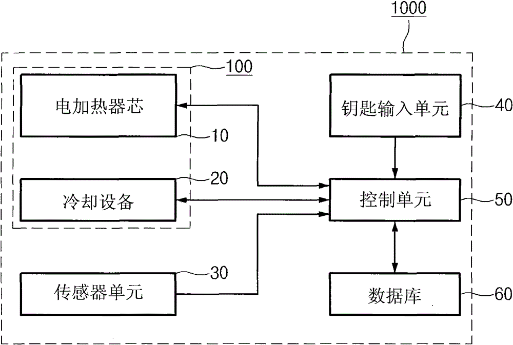
[0045] figure 2 is a block diagram showing the configuration of an air conditioning system 1000 for a vehicle according to the present invention.

[0046] Such as figure 2 As shown in , the air conditioning system 1000 for a vehicle according to the present invention includes a body 100 , an electric heater core 10 , a coolin...


PUM


Abstract

An air conditioning system of a vehicle includes a body, an electric heater core installed within the body and configured to generate a hot air, a cooling device installed within the body and configured to generate a cold air, and a control device configured to control a temperature of the hot air generated by the electric heater core or a temperature of the cold air generated by the cooling device, respectively, by controlling an amount of current applied to the electric heater core or the cooling device according to a difference between an internal temperature or an external ambient temperature of the vehicle and a target temperature, the electric heater core and the cooling device being operated independently of each other.

Description

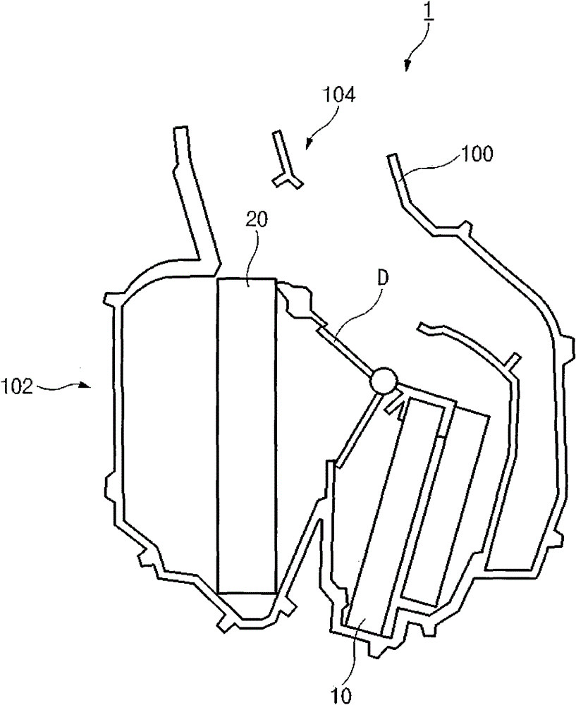
[0001] Cross References to Related Applications [0002] This application claims priority from Korean Patent Application No. 10-2010-0084021 filed on Aug. 30, 2010, the entire contents of which are hereby incorporated by reference for all purposes. technical field [0003] The present invention relates to an air conditioning system in which a heater and a cooler are operated independently in order to control the temperature within a vehicle. Background technique [0004] A vehicle's air conditioning system controls the temperature, humidity, airflow and air cleanliness of the vehicle's interior spaces to achieve the desired conditions. [0005] figure 1 is a side sectional view showing the configuration of a conventional air conditioning system of a vehicle. [0006] Such as figure 1 As shown in , a conventional air conditioner control system 1 equipped with an internal combustion engine (such as a gasoline / diesel engine) includes an air conditioner body 100, a heater cor...

Claims


Application Information

Patent Timeline
Patent Type & Authority Patents(China)
IPC IPC(8): F24F1/00F24F11/02
CPCB60H1/00392B60H1/0005B60H2001/00128B60H2001/00157
Inventor 金勇澈崔载式
Owner HYUNDAI MOTOR CO LTD
Why Eureka
Eureka Blog
Learn More