
Heater core and air conditioner for an automobile equipped with same

a technology for air conditioners and automobiles, applied in lighting, heating apparatus, fluid pressure control, etc., can solve problems such as difficulty in obtaining the proper air flow, undesirable noise, and deterioration of cooling efficiency

Active Publication Date: 2011-04-19
HANON SYST
View PDF4 Cites 0 Cited by
  • Summary
  • Abstract
  • Description
  • Claims
  • Application Information

AI Technical Summary

Benefits of technology

The present invention provides a heater core and an air conditioner for an automobile that can efficiently control the internal temperature of the automobile. The heater core has a flow rate adjusting means that allows for precise adjustment of the amount of cooling water introduced into the heater core based on a user-set temperature. This ensures that the cooling and heating efficiency of the automobile is maximized. The heater core and air conditioner are integrated, eliminating the need for a separate temp door and increasing efficiency. The flow rate adjusting means includes a hollow body, a cover, a ball valve, and a driving means for controlling the amount of cooling water introduced into the heater core. The driving means rotates the ball valve to adjust the flow rate of cooling water based on the cooling and heating needs of the automobile. The air conditioner also includes a case, an evaporator, and a sub-door that can adjust the amount of air passing through the heater core. The sub-door is interlocked with the driving means of the flow rate adjusting means.

Problems solved by technology

In particular, in the air conditioning system for an automobile, since it is generally difficult to secure a sufficient space in an engine room, it is required that the air conditioner for an automobile has a small size and functions to effectively control temperature and air flow.
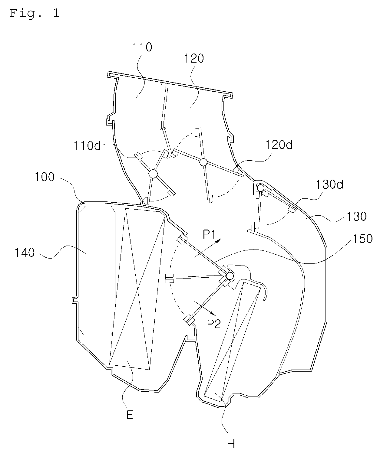
However, in the conventional air conditioner as described above, since the evaporator and the heater core are respectively positioned at specific places, and the temp door for controlling the opening degree of each of the cool air passage and the warm air passage during the air cooling and heating cycle is provided, the space in the engine room corresponding to a radius of operation of the temp door has to be occupied, and further, since the air conditioner has a complicated structure which is an obstacle to the air flow, it is difficult to obtain the proper air flow and there is generated undesirable noise.
Furthermore, since the conventional heater core can not control an amount of cooling water introduced into the heater core, high temperature cooling water may be continuously flowed into the heater core during the air cooling cycle.
Therefore, even though the warm air passage is closed by the temp door, a temperature of the external air is increased by the high temperature cooling water and thus the cooling efficiency is deteriorated.

Method used


Image

  • Heater core and air conditioner for an automobile equipped with same
  • Heater core and air conditioner for an automobile equipped with same
  • Heater core and air conditioner for an automobile equipped with same

Examples


Embodiment Construction

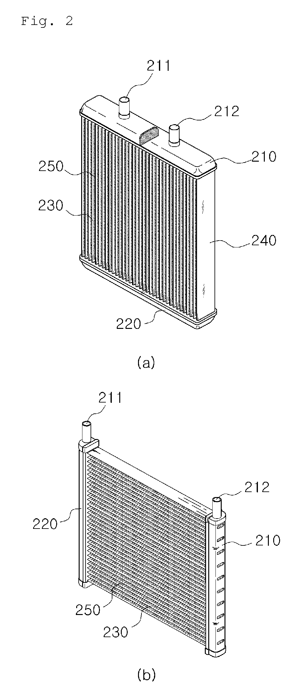
of Main Elements]100: case110, 120, 130: vent110d, 120d, 130d: vent door140: ventilating part150: temp door160: sub-doorE: evaporatorH: heater core210: first tank211: inlet pipe212: outlet pipe220: second tank230: tube240: end plate250: fin300: flow rate adjusting means310: body320: cover330: cooling water introduction part340: bypass line350: ball valve351: first communication part352: second communication part353: driving shaft

BEST MODE FOR CARRYING OUT THE INVENTION

[0028]Practical and presently preferred embodiments of the present invention are illustrative as shown in the following Examples and Comparative Examples.

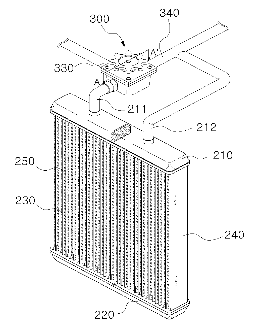
[0029]FIG. 3 is a perspective view of a heater core according to the present invention. Referring to FIG. 3, the heater core H of the present invention includes first and second tanks 210 and 220, inlet and outlet pipes 211 and 212 which are formed at the first tank 210 or second tank 220 and through which cooling water is introduced and discharged, a tube 230 which i...


PUM


Abstract

The present invention relates to a heater core and an air conditioner for an automobile equipped with the same, in which an amount of cooling water introduced into the heater core can be adjusted based on a temperature set by a user, thereby increasing a cooling and heating efficiency.The heater core comprises first and second tanks 210 and 220 which are spaced apart from each other at a predetermined distance; inlet pipe 211 and outlet pipe 212 which are respectively connected to the first tank 210 or second tank 220 and through which cooling water is introduced and discharged; a plurality of tubes 230 of which both ends are respectively fixed between the first and second tanks 210 and 220; a fins 250 which are provided between the tubes 230; a cooling water introduction part 330 which is formed at one side of the inlet pipe 211 and through which the cooling water is introduced; a bypass line 340 which is also formed at one side of the inlet pipe 211 and through which the cooling water is discharged without passing through the heater core H; and a flow rate adjusting means 300 for adjusting an amount of the cooling water introduced into the heater core H.

Description

RELATED APPLICATION[0001]The present application is based on, and claims priority from, KR Application Number 10-2006-0106774, filed Oct. 31, 2006, the disclosure of which is hereby incorporated by reference herein in its entirety.TECHNICAL FIELD[0002]The present invention relates to a heater core and an air conditioner for an automobile equipped with the same, and more particularly, to a heater core and an air conditioner for an automobile equipped with the same, in which an amount of cooling water introduced into the heater core can be adjusted based on a temperature set by a user, thereby increasing a cooling and heating efficiency.BACKGROUND ART[0003]In the recent automotive industry, according as the global interest in environment and energy is increased, there has been performed research and development in the improvement of fuel efficiency. And, in order to satisfy various users' requirements, there has been also proceeded research and development in light, small and multi-fu...

Claims


Application Information

Patent Timeline
Patent Type & Authority Patents(United States)
IPC IPC(8): B60H1/12
CPCB60H1/00571F28D1/05375F28F27/02F28F2250/06F28D2021/0096B60H1/00B60H1/08
Inventor HAN, SEONG SEOK
Owner HANON SYST
Learn More