
Shaped charge retainer system

a technology of retainer and shaped charge, which is applied in the direction of explosive charges, fluid removal, borehole/well accessories, etc., can solve the problems of multiple cumbersome means, serious safety issues, etc., and achieve the effect of convenient use of retainers

Active Publication Date: 2019-11-26
HUNTING TITAN
View PDF9 Cites 2 Cited by
  • Summary
  • Abstract
  • Description
  • Claims
  • Application Information

AI Technical Summary

Benefits of technology

[0008]In order to detonate a shaped charge in a perforating gun a continuous detonating cord is placed adjacent to each shaped charge. Holding a detonating cord in place is crucial to ensuring that all of the shaped charges detonate when the detonating cord detonates. Otherwise, unexploded ordinance may end up being brought to the surface, causing a serious safety issue. Furthermore, current means of fastening the shaped charge to the detonating cord require multiple cumbersome means. This invention aims to provide an efficient, easy to use retainer clip that can firmly attach the detonating cord to a shaped charge.
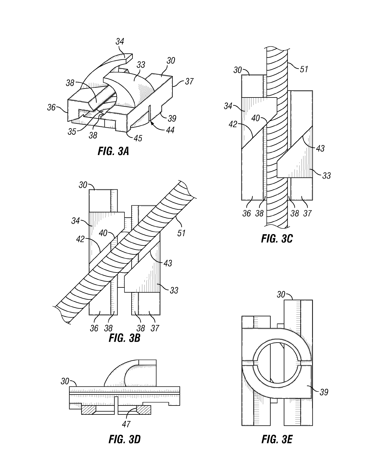
[0009]An example of the invention may include a shaped charge retainer comprising an adaptor for holding a shaped charge, a first interface adapted to engage a charge holder, and a second interface adapted to engage a detonating cord. It may include a third interface adapted to engage a shaped charge. The first interface may have an oblong shape for translating into a matching oblong shaped cutout in the charge holder in a first orientation. The rotation of the shaped charge to a second orientation may substantially eliminate at least one degree of freedom of the shaped charge retainer. The shaped charge retainer may prevent disengaging via the inference of the first interface. The second interface may be a clamp for engaging to a detonating cord by rotating it relative to the detonating cord. The second interface may include a plurality of clamps. The second interface may be a u-shaped retainer. The second interface may be a c-shaped retainer. The second interface may include one or more protrusions adapted to restrain a detonating cord. The first interface may have an oblong shape. The first interface may have a non-circular shape. The first interface may be circular in shape. The first interface may be oblong in shape. The first interface may be polygon in shape. The first interface may be threaded. The first interface may be integrally formed to the charge holder. The third interface may be adapted to snap onto the end of a shaped charge. The third interface may be adapted to thread onto the end of a shaped charge. The third interface may be adapted to mechanically fasten to a shaped charge.

Problems solved by technology

Otherwise, unexploded ordinance may end up being brought to the surface, causing a serious safety issue.
Furthermore, current means of fastening the shaped charge to the detonating cord require multiple cumbersome means.
After the retainer is fitted through the unique shaped hole, it can be rotated, in this case 45 degrees, such that the retainer is in interference with the charge tube and cannot be disengaged.

Method used


Image

  • Shaped charge retainer system
  • Shaped charge retainer system
  • Shaped charge retainer system

Examples


Embodiment Construction

[0033]In the following description, certain terms have been used for brevity, clarity, and examples. No unnecessary limitations are to be implied therefrom and such terms are used for descriptive purposes only and are intended to be broadly construed. The different apparatus, systems and method steps described herein may be used alone or in combination with other apparatus, systems and method steps. It is to be expected that various equivalents, alternatives, and modifications are possible within the scope of the appended claims.

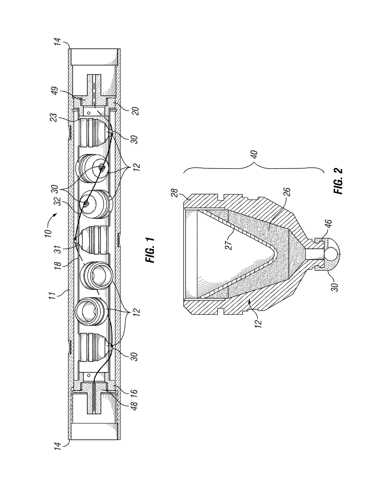
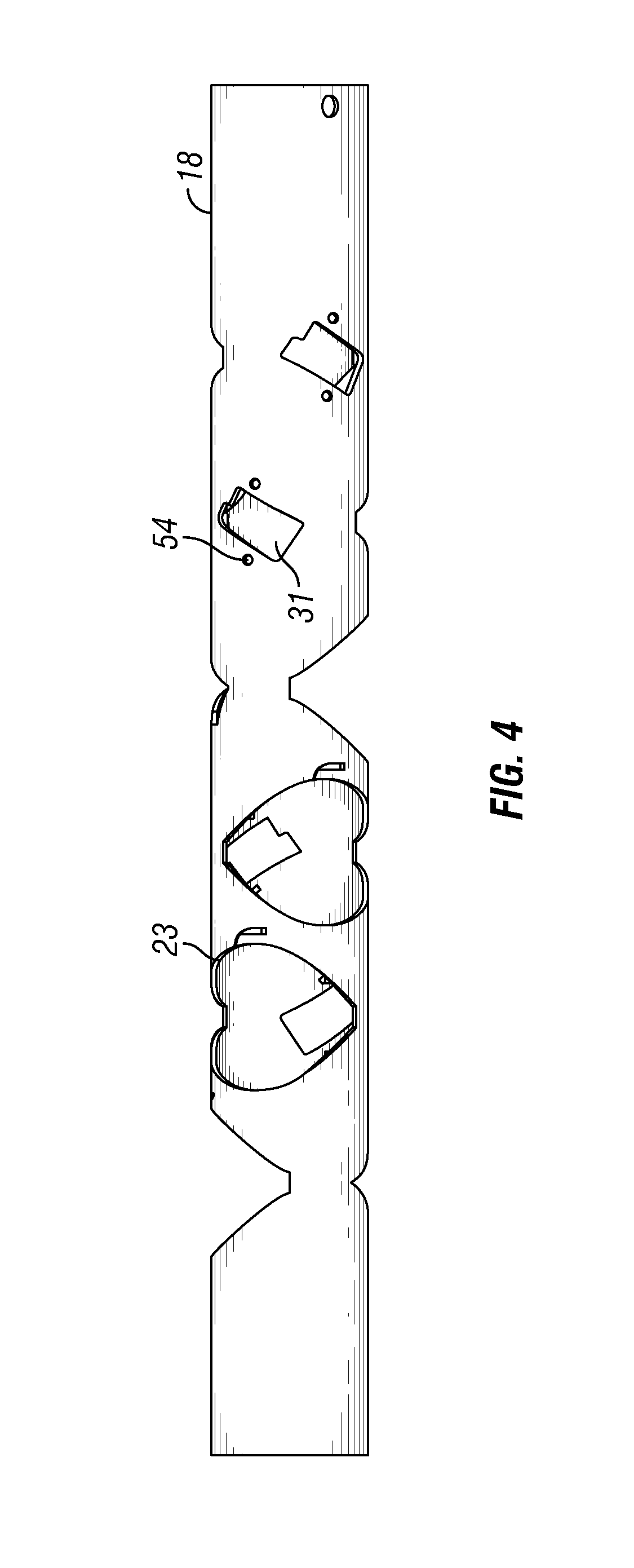
[0034]Referring to an example shown in FIG. 1, a typical perforating gun 10 comprises a gun body 11 that houses the shaped charges 12. The gun body 11 contains end fittings 16 and 20 which secure the charge holder 18 into place. The charge holder 18 in this example is a charge tube and has charge holes 23 that are openings where shaped charges 12 may be placed. The charge holder 18 has retainer cutouts 31 that are adapted to fit a retainer fitting 30 in a pr...


PUM


Abstract

An apparatus and method for locking a detonating cord against a shaped charge.

Description

RELATED APPLICATIONS[0001]This application claims priority to U.S. Provisional Application No. 62 / 001,295, filed May 21, 2014.FIELD[0002]The invention generally relates to perforating guns used in a subterranean environment such as an oil or gas well. More particularly, the invention relates to a fitting that aligns the detonating cord with a shaped charge installed in a carrier tube. The invention has a retainer feature which allows for simplified installation.BACKGROUND OF THE INVENTION[0003]Generally, when completing a subterranean well for the production of fluids, minerals, or gases from underground reservoirs, several types of tubulars are placed downhole as part of the drilling, exploration, and completions process. These tubulars can include casing, tubing, pipes, liners, and devices conveyed downhole by tubulars of various types. Each well is unique, so combinations of different tubulars may be lowered into a well for a multitude of purposes.[0004]A subsurface or subterrane...

Claims


Application Information

Patent Timeline
Patent Type & Authority Patents(United States)
IPC IPC(8): E21B43/116F42B1/036F42D1/04F42B33/02F42B1/02
CPCF42B1/02F42B33/0207F42D1/043F42B1/036E21B43/116
Inventor COLLINS, WILLIAM RICHARDMCDONALD, DEBRA CHRISTINESCHULTE, BRADLEY DEAN
Owner HUNTING TITAN
Learn More