Connector

a technology of connecting rods and connectors, applied in the direction of connection, electrical apparatus, coupling device connection, etc., can solve the problems of dielectric and sub-housing both becoming large in size, cost increase and parts management problems,

Active Publication Date: 2019-11-26
AUTONETWORKS TECH LTD +3
View PDF15 Cites 5 Cited by
  • Summary
  • Abstract
  • Description
  • Claims
  • Application Information

AI Technical Summary

Benefits of technology

[0011]According to the present invention, when changing from the first specification to the second specification, the outer conductor and the dielectric in the first specification are replaced with the sub-housing. That is, even if such replacement is made, the sub-housing is configured so that it can be incorporated into the housing in a retained state, with the result that free change between the first specification and the second specification becomes possible. At this time, since at least the housing in the first specification can be used as it is also in the second specification, it is possible to switch between both specifications while achieving cost reduction.
[0016]According to the above configuration, in the first specification, the swaging piece of the outer conductor is swaged onto the folded-back braided wire to be electrically connected, and the outer cover is swaged to the inner cover via the braided wire, with the result that it is possible to avoid a situation where the outer cover is displaced with respect to the inner cover. Also in the second specification, since the outer cover is swaged to the inner cover by the swaging ring via or not via the braided wire, it is possible to avoid the situation where the outer cover is displaced with respect to the inner cover.

Problems solved by technology

In such a case, if every dedicated connector is set for each grade, cost increase and problems in parts management may occur.
In other words, in a case where each of the dielectric and the sub-housing is not in the divided form but integrally formed, the terminal fitting should be locked inside by elastic locking means such as a lance; in such a form however, there is a need to secure a deflection space of the elastic locking means in the dielectric and the sub-housing, with the result that the dielectric and the sub-housing both become large in size due to such a space.

Method used


Image

  • Connector
  • Connector
  • Connector

Examples


Embodiment Construction

[0036]Next, an embodiment embodying the connector of the present invention will be described with reference to the drawings. The connector of the present embodiment is used for an automatic driving control system of a car, for example, and is a connector realizing miniaturization. In the connector of the present embodiment, it is possible to select either a first specification having the shielding function or a second specification not having the shielding function which will be described below.

[0037]

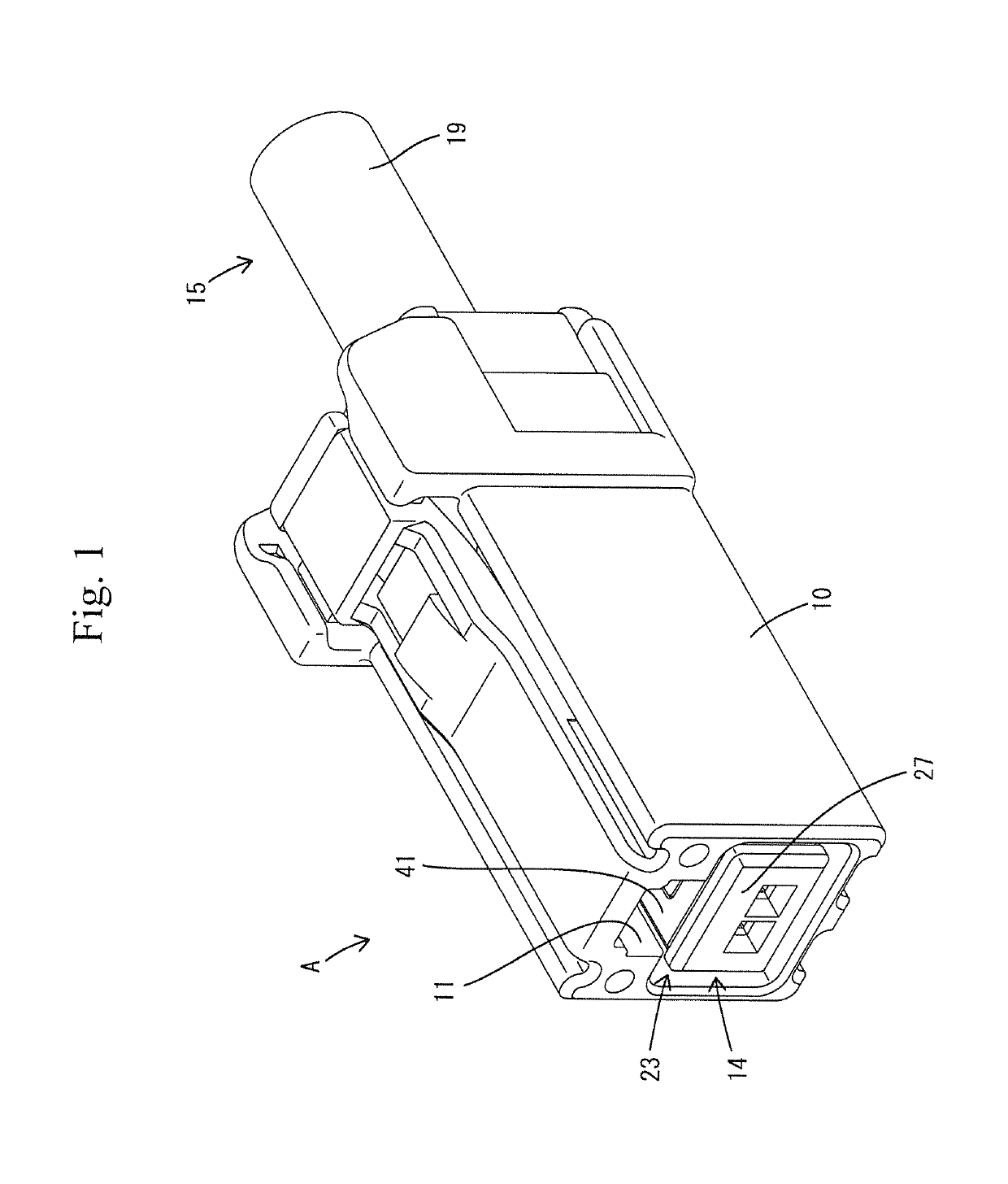
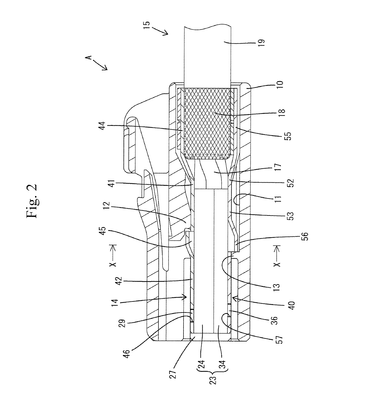
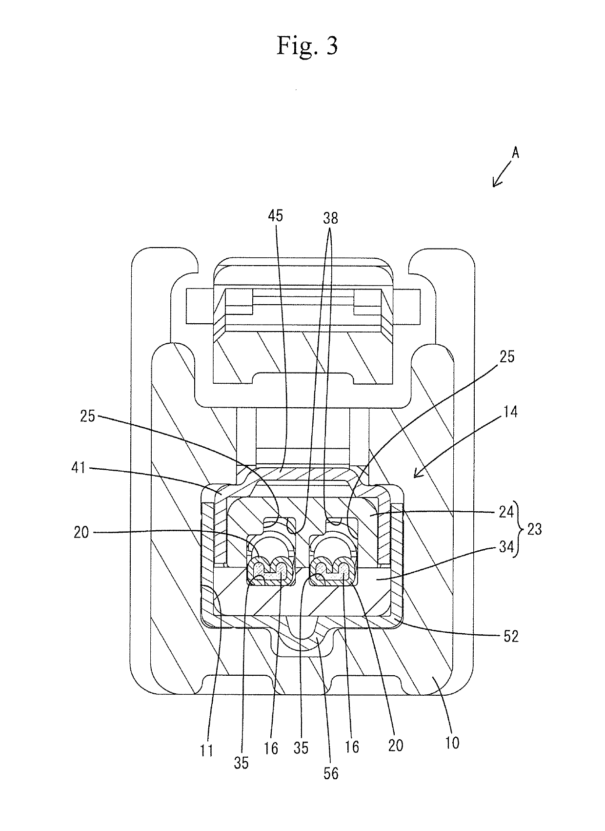
[0038]The first specification is shown in FIGS. 1 to 13. A connector A in the first specification is constructed including a housing 10 and a terminal module 14 (see FIGS. 2 to 5) to be inserted into the housing 10. The terminal module 14 is attached to an end portion of a shielded electric wire 15 and includes a pair of terminal fittings 20, a dielectric 23, and an outer conductor 40.

[0039]In the following description, as for a front-rear direction, the lower left side in FIGS. 1, 4 to...


PUM


Abstract

A connector has parts that can be used in common as much as possible in different specifications to reduce cost and to facilitate parts management. In a first specification having a high shielding function, a terminal fitting (20) connected to a shielded electric wire (15) is accommodated in a dielectric (23). The dielectric (23) is surrounded by an outer conductor (40) that is connected to a braided wire (18). The second specification requires no shielding function, and thus the outer conductor (40) is not used. Rather, a sub-housing (70) having the same shape and size as the outer conductor (40) of the first specification is used. The sub-housing (70) is configured to accommodate and retain the terminal fitting (20) and is locked in a same retained state as in the first specification when accommodated in a common housing (10) used in both specifications.

Description

BACKGROUND[0001]Field of the Invention[0002]The present invention relates to a connector.[0003]Description of the Related Art[0004]Japanese Patent Application Publication No. 2002-319456 discloses a connector having a shielding function. This connector incorporates a terminal fitting connected to an end portion of a shielded wire, a dielectric for accommodating the terminal fitting, and an outer conductor connected to the terminal fitting while surrounding the dielectric, and thereby exhibits a high shielding function.[0005]Depending on the grade of the vehicle type, however, a high shielding function may not be required for a connector. In such a case, if every dedicated connector is set for each grade, cost increase and problems in parts management may occur.[0006]The present invention has been accomplished on the basis of the above circumstances, and an object of the present invention is to provide a connector in which parts can be used in common as much as possible in different ...

Claims


Application Information

Patent Timeline
Patent Type & Authority Patents(United States)
IPC IPC(8): H01R4/70H01R13/6581H01R13/436H01R13/516H01R13/6592H01R103/00
CPCH01R13/516H01R13/6592H01R13/4361H01R13/6581H01R2103/00
Inventor MATSUI, HAJIMEOMORI, YASUOMAESOBA, HIROYOSHIICHIO, TOSHIFUMIOKUMURA, KIMIYASUTABATA, MASAAKIYAMAZAKI, RYUTAROKOBAYASHIHARA, MOTOYA
Owner AUTONETWORKS TECH LTD
Why Eureka
Try Eureka