VGT for vehicle

a technology of variable geometry and turbocharger, which is applied in the direction of combustion engines, machines/engines, engine fuction, etc., can solve the problem of relatively slow catalyst temperature rise, and achieve the effect of maximizing purification performan

Active Publication Date: 2019-12-17
HYUNDAI MOTOR CO LTD +1
View PDF13 Cites 0 Cited by
  • Summary
  • Abstract
  • Description
  • Claims
  • Application Information

AI Technical Summary

Benefits of technology

[0006]Various aspects of the present invention are directed to providing a VGT for a vehicle, the VGT being configured to properly adjust the angle of the vanes according to each operation region in all the operation regions of the engine, and also allow the exhaust gas to directly heat the catalyst by bypassing the turbine wheel only by adjusting the angle of the vanes at an initial stage of cold-starting of the engine, whereby it is possible to maximize the purification performance for removal of in the exhaust gas at the initial stage of cold-start of engine by rapid catalyst activation.
[0009]The side guide of each of the vanes may be formed in a plate shape integrally protruding radially with respect to a rotation axis of the vanes, to minimize cross-sectional area reduction of the variable nozzle formed by the vanes.
[0012]A portion where the disk portion and the hollow portion are connected may be formed to have a cross-sectional shape forming a predetermined air gap with a spatial trajectory formed when a turbine blade of the turbine wheel is rotated, and the air gap may be minimized within a range preventing interference between the turbine blade and the disk body.
[0014]According to an exemplary embodiment of the present invention, it is possible to properly adjust the angle of the vanes according to each operation region in all the operation regions of the engine, and also it is possible to allow the exhaust gas to directly heat the catalyst by bypassing the turbine wheel only by adjusting the angle of the vanes at an initial stage of cold-starting of the engine, whereby it is possible to maximize the purification performance for removal of harmful substances in the exhaust gas at the initial stage of cold-start of engine by rapid catalyst activation.

Problems solved by technology

However, a vehicle provided with a conventional VGT is problematic in that since the exhaust gas is supplied to the catalyst only through the turbine wheel, even if the vanes are fully opened, the exhaust gas reaches the catalyst in the state where the energy thereof is reduced to some extent by the turbine wheel, and thus the temperature rise of the catalyst is relatively slow compared to the case where the exhaust gas is supplied directly to the catalyst without going through the turbine wheel.

Method used


Image

  • VGT for vehicle
  • VGT for vehicle
  • VGT for vehicle

Examples


Embodiment Construction

[0028]Reference will now be made in detail to various embodiments of the present invention(s), examples of which are illustrated in the accompanying drawings and described below. While the invention(s) will be described in conjunction with exemplary embodiments of the present invention, it will be understood that the present description is not intended to limit the invention(s) to those exemplary embodiments. On the other hand, the invention(s) is / are intended to cover not only the exemplary embodiments of the present invention, but also various alternatives, modifications, equivalents and other embodiments, which may be included within the spirit and scope of the invention as defined by the appended claims.

[0029]Hereinbelow, an exemplary embodiment of the present invention will be described in more detail with reference to the accompanying drawings.

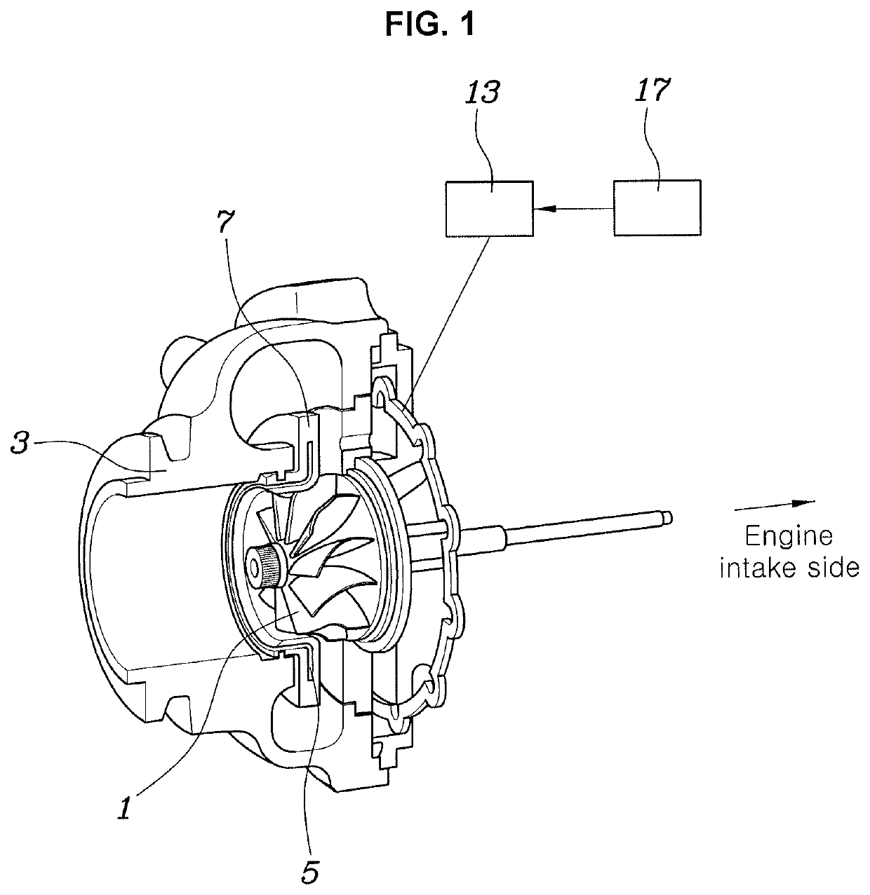
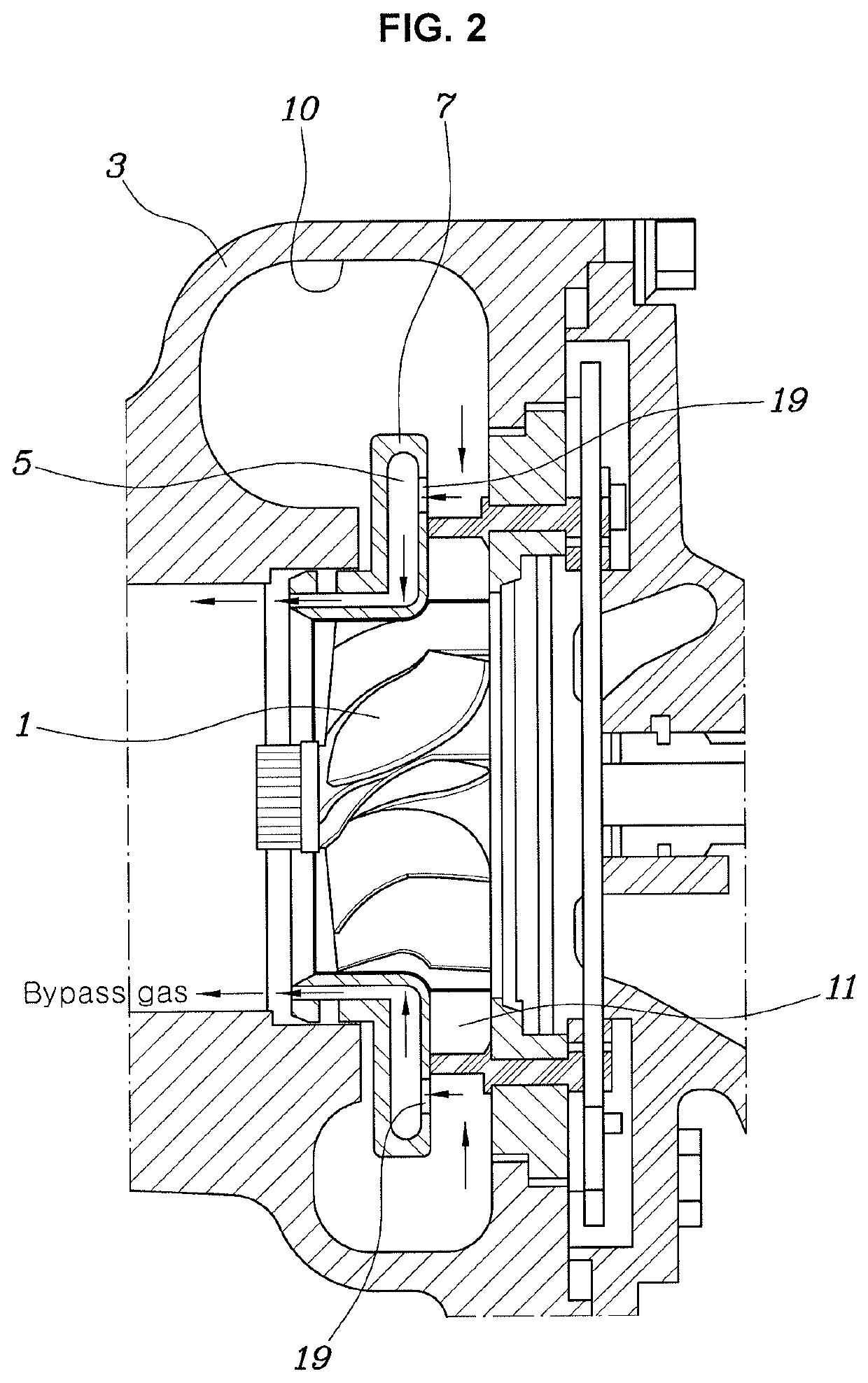
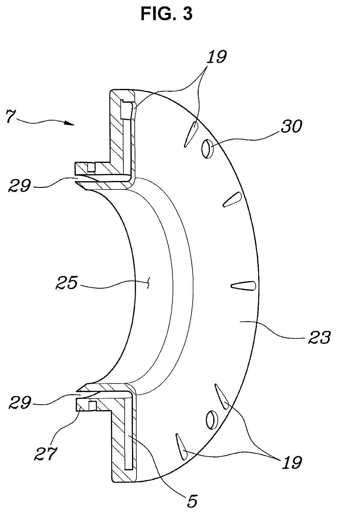
[0030]Referring to FIGS. 1 to 10, a variable geometry turbocharger (VGT) for a vehicle according to an exemplary embodiment of the pres...


PUM


Abstract

A variable geometry turbocharger (VGT) for a vehicle, may include a turbine wheel; a turbine housing configured to rotatably support the turbine wheel, and provided with a passage for receiving exhaust gas from a radially external side of the turbine wheel and discharging the exhaust gas in an axial direction of the turbine wheel; a disk body provided in the passage of the turbine housing, and provided therein with a bypass line such that the exhaust gas bypasses the turbine wheel; and a plurality of vanes provided between the disk body and the turbine housing to form a variable nozzle for controlling a flow of the exhaust gas flowing radially inwardly of the turbine wheel.

Description

CROSS REFERENCE TO RELATED APPLICATION[0001]The present application claims priority to Korean Patent Application No. 10-2018-0051748, filed May 4, 2018, the entire contents of which is incorporated herein for all purposes by this reference.BACKGROUND OF THE INVENTIONField of the Invention[0002]The present invention relates generally to a variable geometry turbocharger (VGT) for a vehicle. More particularly, the present invention relates to a technology for a VGT structure.Description of Related Art[0003]A VGT of a vehicle changes the flow of exhaust gas entering a turbine wheel by adjusting an angle of vanes to actively cope with changes in operating conditions of an engine, whereby it is possible to provide a supercharging performance suitable for the entire engine operation region such by as reducing the turbo lag in the low load region to increase responsiveness.[0004]Meanwhile, a catalyst for purifying harmful substances in the exhaust gas may rapidly reach the light-off tempera...

Claims


Application Information

Patent Timeline
Patent Type & Authority Patents(United States)
IPC IPC(8): F02B37/18F01D17/16F01D9/04F02B37/24
CPCF01D17/165F01D9/041F01D9/048F02B37/183F02B37/24F05D2260/85F05D2240/128F05D2220/40F05D2240/14F02B37/18F01D17/105F01D25/24Y02T10/12
Inventor JIN, SEOK BEOM
Owner HYUNDAI MOTOR CO LTD
Why Eureka
Try Eureka