Protective shroud for a dive watch

a protection shroud and watch technology, applied in the field of dive watch protection shrouds, can solve problems such as dial siz

Active Publication Date: 2019-12-17
CRESSI SUB
View PDF11 Cites 5 Cited by
  • Summary
  • Abstract
  • Description
  • Claims
  • Application Information

AI Technical Summary

Benefits of technology

[0013]Advantageously, the thickness of such rib, which distances the lenticular element from the dial, and the lenticular shap

Problems solved by technology

It is therefore necessary for such information to be clearly visible on the watch dial and, in a known way, greater visibility may be obtained with an inc

Method used


Image

  • Protective shroud for a dive watch
  • Protective shroud for a dive watch

Examples


Embodiment Construction

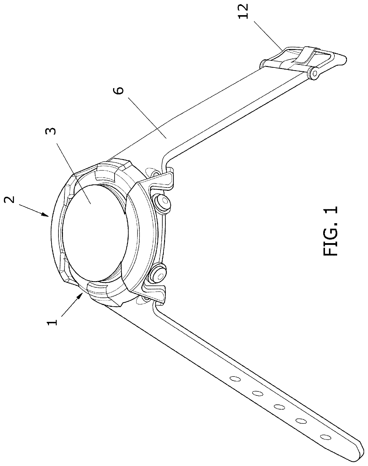
[0019]With reference to the figures mentioned, a dive watch is shown indicated overall with the reference number 1.

[0020]The dive watch 1 comprises in a known way a case 10 that supports a dial 4 surmounted by a protective crystal 11, and a strap 6 equipped with a buckle 12 for fastening the watch 1 to the wrist of the diver.

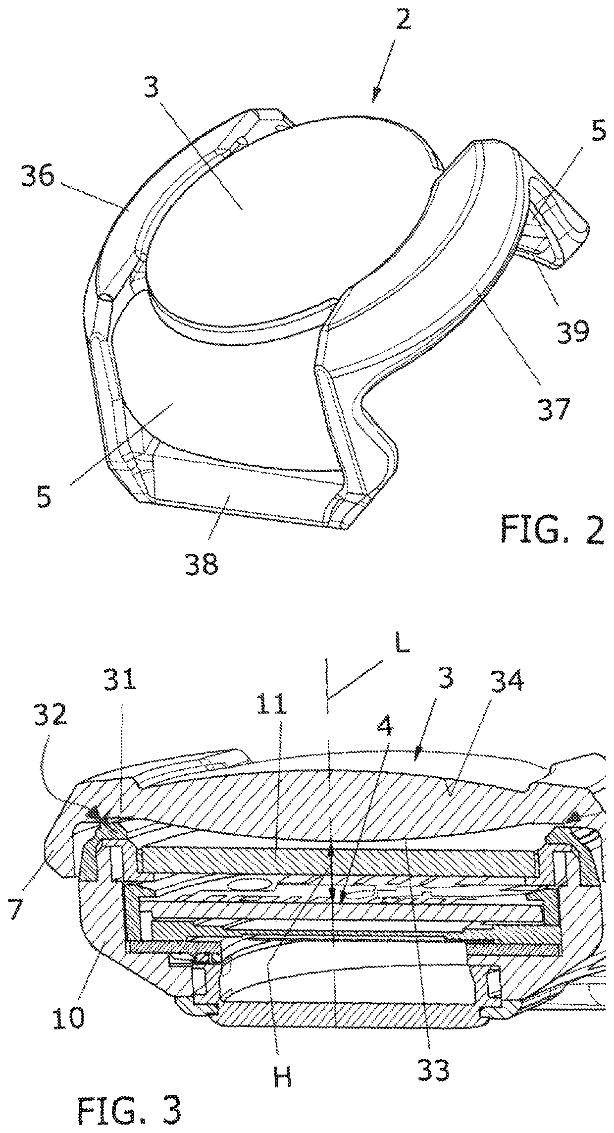
[0021]A protective shroud 2 made of elastic material is fitted onto the watch 1.

[0022]The protective shroud 2, being made of elastic material, can be easily fitted and removed from the watch 1 as needed.

[0023]The protective shroud 2 advantageously comprises a transparent lenticular element 3 configured to enlarge the image that appears on the dial 4 of the watch 1 and to cover it and protect it.

[0024]The lenticular element 3 is convex and is arranged with its optical axis L positioned orthogonally to the dial 4 of the watch 1.

[0025]As shown in particular, the lenticular element 3 is bi-convex, in the sense that both faces 33, 34 of the lenticular element 3 are c...


PUM


Abstract

A protective shroud for a dive watch having a transparent lenticular element configured to enlarge an image appearing on a dial of the dive watch. The shroud can include a rib that distances the lenticular element from the dial, and a flange that extends around the lenticular element and includes two slots for fixing a strap of the dive watch. The shroud can be made of a single piece of elastic material.

Description

RELATED APPLICATIONS[0001]This application claims priority to Italy Application No. 102016000099468, filed Oct. 4, 2016. The above-identified related application is incorporated by reference.FIELD OF USE[0002]The present invention relates to a protective shroud for a dive watch.BACKGROUND OF THE INVENTION[0003]Dive watches are generally equipped with a protective shroud made of transparent elastic material that protects them from the inevitable impacts that they may undergo during diving activity but that allows the visibility of the dial.[0004]Such protective shrouds generally comprise a protective element for protecting the dial and two projecting slots that allow the passage of a strap in a single piece or the fixing of the two parts thereof.[0005]Dive watches are often actual calculators and, in that case, on their dials, numerous pieces of information appear that are necessary for managing the diver's activities and for his / her safety.[0006]It is therefore necessary for such in...

Claims


Application Information

Patent Timeline
IPC IPC(8): G04B43/00G02B25/00G04B47/06G04G21/02
CPCG04G21/02G02B25/002G04B43/002G04B47/06G04B39/008G04B43/00G04B37/005G04G17/08
Inventor GODOY, CARLOS ALBERTO
Owner CRESSI SUB
Why Eureka
Try Eureka