Supercharge Your Innovation With Domain-Expert AI Agents!

Pump assembly

a technology of pump assembly and assembly plate, which is applied in the direction of heating apparatus, heating types, applications, etc., can solve problems such as unfavorable system nois

Active Publication Date: 2019-12-24
GRUNDFOS HLDG
View PDF20 Cites 0 Cited by
  • Summary
  • Abstract
  • Description
  • Claims
  • Application Information

AI Technical Summary

Benefits of technology

The design of this invention helps to minimize water hammer and other issues caused by starting up a pump. It does this by making sure that there is no flow through the pump's exits when it is turned off. This is done by making the exits closed in the idle position. The design also allows for an annular space around the pump's impeller, which helps to create a flow that can move the valve elements in the pump. Overall, this design helps to make starting up a pump smoother and more efficient.

Problems solved by technology

The problem of switching the heating water circuit between two flow paths, specifically once through a heating circuit in the building and once through a heat exchanger for heating service water, arises in heating facilities, in particular compact heating facilities.
Water hammers which lead to undesirable noises in the system are a problem with such designs.

Method used


Image

  • Pump assembly
  • Pump assembly
  • Pump assembly

Examples


Embodiment Construction

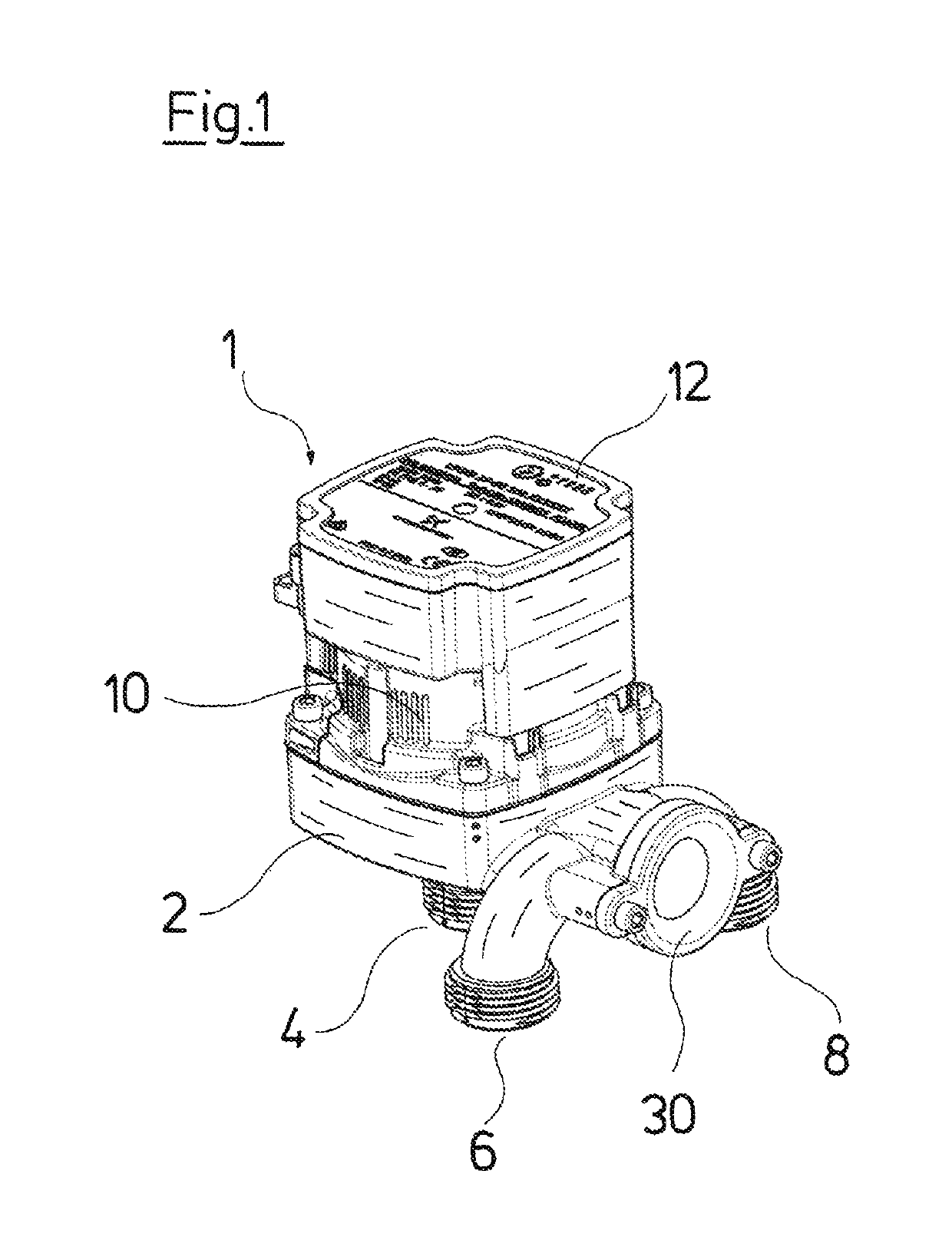
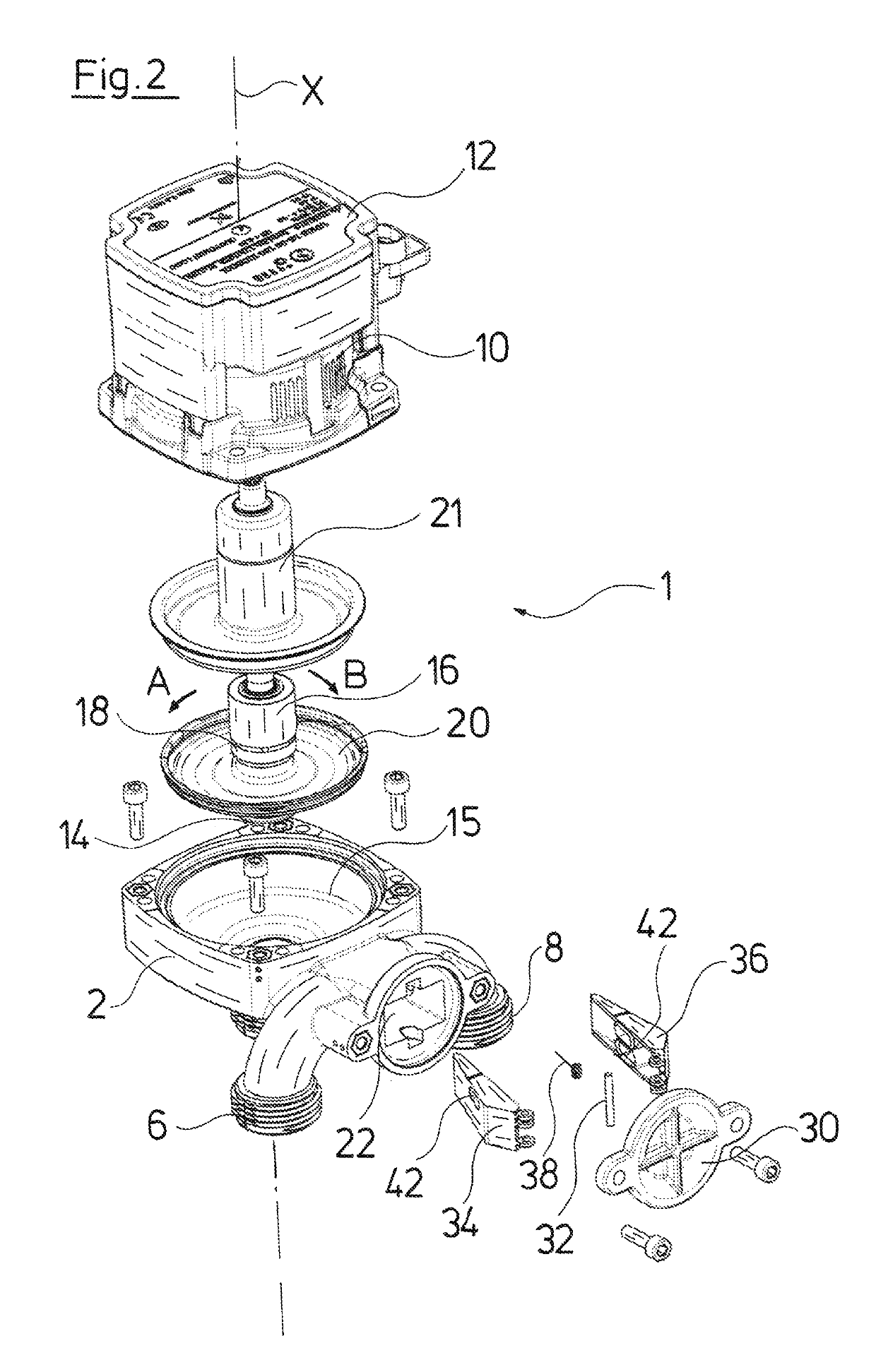
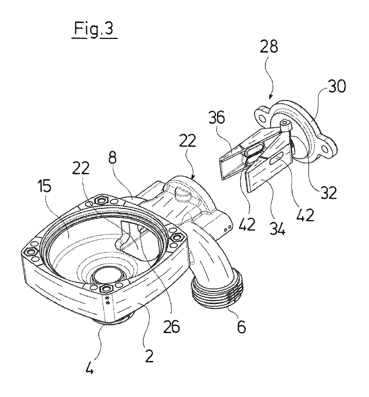
[0046]Referring to the drawings, the pump assembly 1, which is represented in the figures, is configured as a circulation pump assembly with a wet-running electrical drive motor. The pump assembly 1 comprises a pump casing 2 which can be configured as a molded component of metal or plastic. The pump casing 2 comprises a suction connection 4 and two delivery branches 6 and 8. A motor or stator casing 10, in which the electrical drive motor is arranged, is applied onto the pump casing 2. An electronics housing 12, in which a control and regulation device for the control of the electrical drive motor is arranged, is arranged on the axial end of the stator casing 10 which is away from the pump casing 2.

[0047]As can be recognized in the exploded view according to FIG. 2, an impeller 14 which is connected to the rotor 16 of the electrical drive motor in a rotationally fixed manner is arranged in the inside of the pump casing 2. The rotor 16 is rotatably held in a bearing 18, which is fixe...


PUM


Abstract

A pump assembly includes pump casing (2), an impeller (14) rotatably arranged in the pump casing, a two rotation directions (A, B) electrical drive motor connected to drive the impeller and a valve arrangement (28) arranged in the pump casing to switch a flow path downstream of the impeller between two exits (24, 26) of the pump casing, depending on a rotation direction of the impeller. The valve arrangement includes a first movable valve element (34) at a first exit (24) and a second movable valve element (36) at a second exit (26). The first valve element partly closes the first exit in a closed position and is movable into an opened position by flow in the first rotation direction and the second valve element partly closes the second exit in a closed position and is movable into an opened position by flow in the second rotation direction (B).

Description

CROSS REFERENCE TO RELATED APPLICATIONS[0001]This application claims the benefit of priority under 35 U.S.C. § 119 of European Application 16 178 585.2 filed Jul. 8, 2016, the entire contents of which are incorporated herein by reference.FIELD OF THE INVENTION[0002]The invention relates to a pump assembly with a pump casing, with an impeller which is rotatably arranged in the pump casing, with an electrical drive motor which is connected to the impeller for the drive of the impeller and which is selectively driveable in two rotation directions, as well as with a valve arrangement which is arranged in the pump casing and is designed to switch a flow path downstream of the impeller between two exits formed in the pump casing, in a manner depending on the rotation direction of the impeller.BACKGROUND OF THE INVENTION[0003]The problem of switching the heating water circuit between two flow paths, specifically once through a heating circuit in the building and once through a heat exchang...

Claims


Application Information

Patent Timeline
Patent Type & Authority Patents(United States)
IPC IPC(8): F04D15/00F04D29/48F24D3/10F04D13/06F04D29/08F04D29/22F04D29/42
CPCF04D29/22F04D29/486F04D29/2283F24D3/105F04D13/0606F04D29/4293F04D13/06F04D15/0016F04D29/086F05D2250/52Y10S415/911
Inventor JENSEN, OLAVHANSEN, OLEDØSSING, BENTGREVE, ROBERT
Owner GRUNDFOS HLDG
Features
  • R&D
  • Intellectual Property
  • Life Sciences
  • Materials
  • Tech Scout
  • Unparalleled Data Quality
  • Higher Quality Content
  • 60% Fewer Hallucinations
Learn More