Eureka AIR delivers breakthrough ideas for toughest innovation challenges, trusted by R&D personnel around the world.

Image heating apparatus and image forming apparatus that correct an amount of current supplied to a plurality of heat generating resistors using detected temperatures

a technology of heat generation resistors and heating apparatus, which is applied in the direction of electrographic process apparatus, instruments, optics, etc., can solve the problems of image failure, such as fixing failure in low temperature areas, and the inability to generate desired longitudinal temperature distribution by a predetermined timing, so as to reduce the fpot, suppress the variation of temperature rising, and output good image

Active Publication Date: 2019-12-24
CANON KK
View PDF8 Cites 1 Cited by
  • Summary
  • Abstract
  • Description
  • Claims
  • Application Information

AI Technical Summary

Benefits of technology

[0005]It is an object of the present invention to provide a technique to decrease the FPOT and to acquire a good output image by suppressing the variation of the temperature rising in each heating region of the image heating apparatus when the fixing start up control is performed.
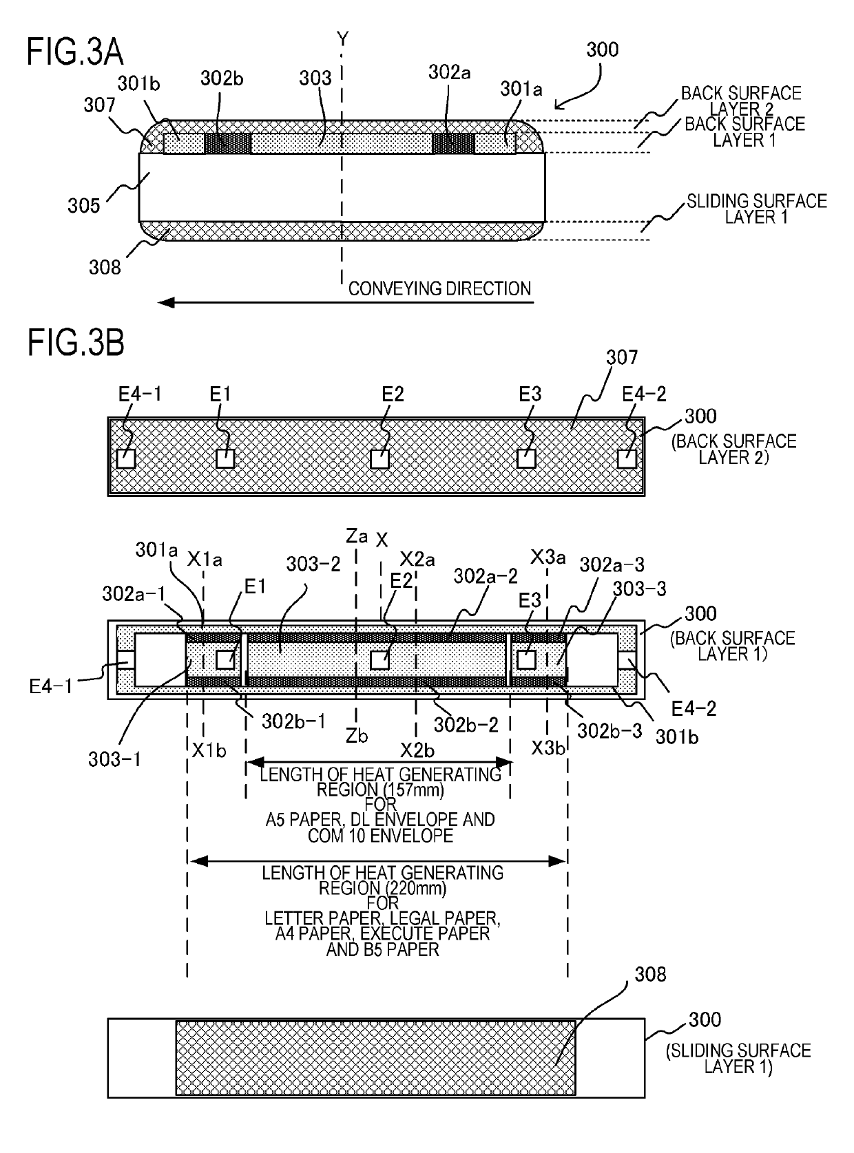
[0006]In one aspect, the present invention provides an image heating apparatus that includes an image heating portion that includes a heater constituted of a substrate and a plurality of heat generating elements disposed on the substrate in a longitudinal direction of the substrate, and that is configured to heat an image formed on a recording material by using the heat of the heater, a power supply control portion configured to control power to be supplied to the plurality of heat generating elements so as to selectively heat a plurality of heating regions corresponding to the plurality of heat generating elements, respectively, a plurality of temperature detecting portions configured to detect temperature of each of the plurality of heating regions, and a current amount correcting portion configured to correct an amount of current that the power supply control portion supplies to the plurality of heat generating elements, wherein the current amount correcting portion corrects the current amount, based on the temperature detected by each of the plurality of temperature detecting portions, so that a difference of a temperature rising amount per unit time among the plurality of heating regions at the start of an image heating operation becomes small.
[0008]According to the present invention, the FPOT can be decreased and a good output image can be acquired by suppressing the variation of the temperature rising in each heating region of the image heating apparatus when the fixing start up control is performed.

Problems solved by technology

If the temperature in the non-paper passing portion increases too much, each component inside the apparatus is more easily damaged.
In the configuration of Japanese Patent Application Publication No. 2015-194713, however, if the temperature rising speed of each heating region varies when the image heating apparatus is heated up to a predetermined temperature when the print operation is started (when the fixing start up control is performed), a desired temperature distribution in the longitudinal direction may not be generated by a predetermined timing when the recording material is fed.
If a recording material is passed in a state in which a desired temperature distribution in the longitudinal direction is not generated, an image failure, such as a fixing failure in low temperature areas, may be generated.
Further, if feeding the recording material to the image heating apparatus is delayed until a desired temperature distribution in the longitudinal direction is generated, a first print out time (FPOT) may be delayed.

Method used


Image

  • Image heating apparatus and image forming apparatus that correct an amount of current supplied to a plurality of heat generating resistors using detected temperatures
  • Image heating apparatus and image forming apparatus that correct an amount of current supplied to a plurality of heat generating resistors using detected temperatures
  • Image heating apparatus and image forming apparatus that correct an amount of current supplied to a plurality of heat generating resistors using detected temperatures

Examples


example 1

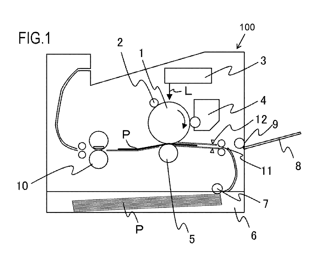
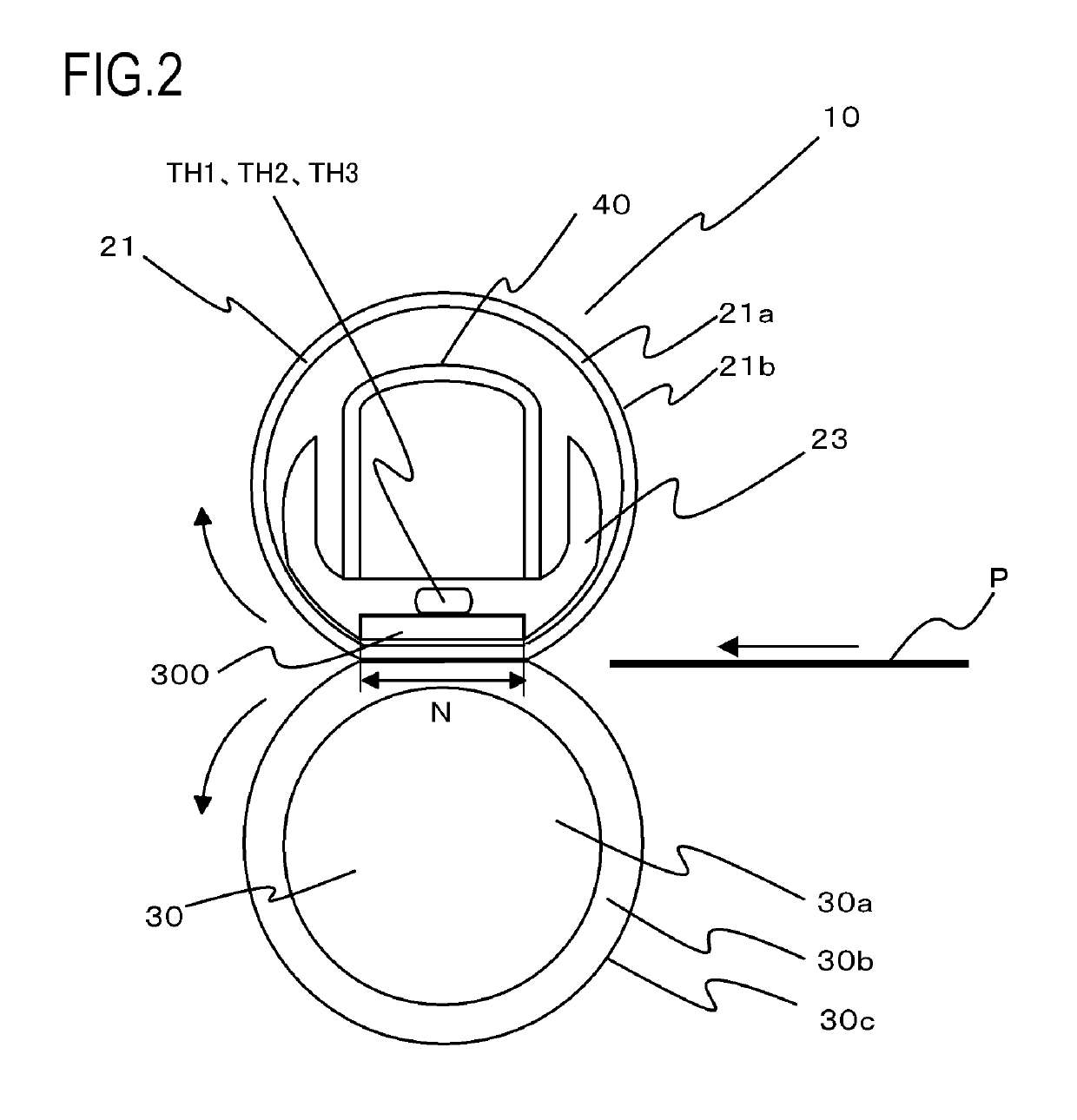
[0028]FIG. 1 is a schematic cross-sectional view depicting a general configuration of a laser beam printer (hereafter “laser printer”) 100, which is an image forming apparatus according to an example of the present invention. A photosensitive drum 1 is rotationally driven in the arrow direction, and the surface of the photosensitive drum 1 is uniformly charged by a charging roller 2, which is a charging apparatus. A laser scanner 3 scans and exposes the surface of the photosensitive drum 1 using a laser beam L, of which ON / OFF is controlled in accordance with the image information, so as to form an electrostatic latent image (latent image forming process). A developing apparatus 4 allows toner to adhere to this electrostatic latent image, and develops the toner image onto the photosensitive drum 1 (developing process). In a transfer nip portion in which a transfer roller 5 and the photosensitive drum 1 are pressure-contacted, the toner image formed on the photosensitive drum 1 is tr...


PUM


Abstract

An image heating apparatus includes a heater having a plurality of resistors, and a power supply control circuit that controls power supplied to the plurality of resistors so as to selectively heat a plurality of heating regions. A plurality of thermistors detect a temperature of each of a plurality of regions of the image heater, and a processor functions as a current amount correcting portion that corrects an amount of current supplied to the plurality of resistors. The current amount is corrected based on the temperature detected by each of the plurality of thermistors, so that a difference of a temperature rising amount per unit time among the plurality of heating regions at the start of an image heating operation becomes small and a total amount of power supplied to the plurality of heat generating elements is kept to within a predetermined limited power amount.

Description

[0001]This application claims the benefit of Japanese Patent Application No. 2017-151519, filed on Aug. 4, 2017, which is hereby incorporated by reference herein in its entirety.BACKGROUND OF THE INVENTIONField of the Invention[0002]The present invention relates to an image heating apparatus, such as a fixing unit installed in an image forming apparatus (e.g. copier, printer), which uses an electrophotographic system or an electrostatic recording system, or a gloss applying apparatus that improves the gloss value of a toner image by reheating a fixed toner image on a recording material. The present invention also relates to an image forming apparatus equipped with this image heating apparatus.Description of the Related Art[0003]As an image heating apparatus installed in such an image forming apparatus, such as a copier and a laser beam printer, a film heating type image heating apparatus, which excels in on demand use, has been widely used (Japanese Patent Application Publication No...

Claims


Application Information

Patent Timeline
Patent Type & Authority Patents(United States)
IPC IPC(8): G03G15/20G03G15/00
CPCG03G15/00G03G15/20G03G15/2042G03G15/2039G03G2215/2035G03G15/80
Inventor TAKAGI, KENJI
Owner CANON KK
Why Eureka
Eureka Blog
Learn More