Coffee grinder and coffee grinding method

a coffee grinder and coffee technology, applied in the field of coffee grinders, can solve the problems of stall condition, lack of solution, heavy power motor, etc., and achieve the effects of low cost, high rotation rate of grinding tools, and limited motor power

Active Publication Date: 2019-12-31
VERSUNI HLDG BV
View PDF26 Cites 2 Cited by
  • Summary
  • Abstract
  • Description
  • Claims
  • Application Information

AI Technical Summary

Benefits of technology

[0027]An advantage of the present invention is that the grinding degree, i.e. the fineness or coarseness of the coffee grind, does not have to be changed. Thus, the coffee grinder can continue operation after a temporary reversal with the same grinding degree.
[0028]As a further advantage, a lighter, smaller and potentially less expensive motor can be used. The present invention is particularly advantageous for novel types of coffee grinders having a limited motor power and operating at high rotation rates of the grinding tool. Since the power of a motor is given by the torque times the rotation rate, the limitation of power in combination with high rotation rates of the grinding tool also mean that the torque for driving the grinding tool is limited. In conventional coffee grinders, a gearing having a gearing ratio of 1:40 between motor and grinding tool is often used. A high gearing ratio can provide sufficient torque at the grinding tool that a stall condition does not occur. However, a gearing is expensive, bulky and inefficient in energy. It would thus be advantageous to use no gearing at all or a light, compact and less expensive gearing, for example having a much lower gearing ratio of, for example, 1:7, 1:5, or even 1:3.
[0029]As used herein, the term “grinding tool” or grinding mill refers to an element configured to reduce the size of coffee beans preferably by a rotary movement such as a movable grinding burr which is configured to interact with a second grinding burr to reduce the size of coffee beans. The optional second grinding burr can be static. Further, the term “grinding tool” refers to a grinding tool having an abrasive surface, wherein the coffee beans and the abrasive surface are made to contact each other and to perform a relative movement with respect to each other, such that the coffee beans are ground off bit by bit by a grinding or scraping movement. Blade grinders are a further alternative.
[0030]As used herein, the term “stall condition” refers to a state wherein the coffee grinder is blocked by jammed beans, bean particles and / or coarse grind, in particular a state wherein the grinding tool comes to a complete stop. Further, the term “stall condition” refers to a condition wherein a torque required to operate the grinding tool of the coffee grinder exceeds a predetermined threshold but not yet coming to a complete stop. This may cause an overheating of the motor for driving the grinding tool. In an embodiment, the condition is evaluated and used to prevent an overheating of the motor driving the grinding tool.
[0031]As used herein, the term “coffee grinder” is used as a class terminology also comprising grinders for grinding other beans, grains or seeds such as soy beans or poppy seeds. Further, the grinder can be configured to receive and further reduce the size of coarse grind, thus of an intermediate product. The same applies for the expression “grinding tool for grinding coffee beans”.
[0032]According to a preferred embodiment, the reversal unit comprises a controller for controlling a direction of rotation of the motor. Thereby, the motor can be actively turned back by the reversal unit. If the grinding tool and the motor are rigidly coupled, this also reverses a direction of rotation of the grinding tool. Thus, the drive train from the motor to the grinding tool is configured for reversal. An advantage of this embodiment is that it can be implemented as an all electronic solution without the need for additional mechanical elements.

Problems solved by technology

A possible failure condition occurs if the coffee grinder is blocked by jammed beans, bean particles or coarse grind.
EP 2 030 539 A1 teaches to consequently shut of the motor before it is damaged but does not provide a solution to overcome the stall condition.
A disadvantage of this solution is that a powerful motor is heavy, bulky and / or expensive.
A disadvantage of this solution is that it requires manually adjusting the separation of the burrs and clearing the coffee grinder which is a tedious and time-consuming process.

Method used


Image

  • Coffee grinder and coffee grinding method
  • Coffee grinder and coffee grinding method
  • Coffee grinder and coffee grinding method

Examples


Embodiment Construction

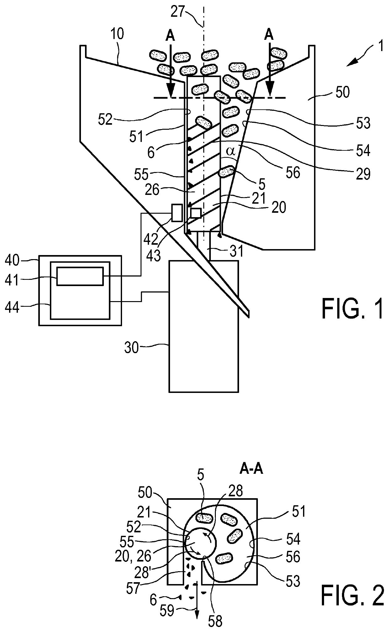
[0055]FIG. 1 shows an exemplary embodiment of a coffee grinder 1. The coffee grinder 1 comprises a grinding tool 20 for grinding coffee beans, a motor 30 for driving the grinding tool 20, a stall detector 41 for detecting a stall condition of the grinding tool 20 and / or of the motor 30, and a reversal unit 40 configured to temporarily reverse a direction of rotation of the grinding tool 20 and / or of the motor 30 if the stall detector 41 detects a stall condition, as the basic components.

[0056]A coffee grinder 1 is a device for grinding coffee beans 5, which are diagrammatically shown in FIG. 1 as ellipses. By grinding the coffee beans 5, coffee powder or coffee grind is formed, which is suitable to be used in a process of making coffee by allowing a quantity of water to interact with the coffee grind, so that the soluble part of the coffee grind is extracted. The coffee grinder 1 can also be fed with coarse coffee grind. The coffee grinder 1 can be an integral part of a coffee maker...


PUM


Abstract

A coffee grinder having a grinding tool (20) for grinding coffee beans, a motor (30) for driving the grinding tool (20), a stall detector (41) for detecting a stall condition of the grinding tool (20) and / or of the motor (30), and a reversal unit (40) configured to temporarily reverse a direction of rotation (28,28′) of the grinding tool (20) and / or of the motor (30) if the stall detector (41) detects a stall condition. Further, a corresponding coffee grinding method and a coffee machine having a coffee grinder are presented.

Description

[0001]This application is the U.S. National Phase application under 35 U.S.C. § 371 of International Application No.PCT / EP2014 / 074233, filed on Nov. 11, 2014, which claims the benefit of International Application No. 13192472.2 filed on Nov. 12, 2013. These applications are hereby incorporated by reference herein.FIELD OF THE INVENTION[0002]The present invention relates to a coffee grinder. The present invention further relates to a coffee grinding method and a coffee machine comprising the coffee grinder.BACKGROUND OF THE INVENTION[0003]A coffee grinder is a device for grinding coffee beans, for example, for brewing coffee. A coffee grinder comprises a grinding tool for grinding coffee beans and a motor for driving the grinding tool. A coffee grinder can be a stand-alone device or integrated, for example, in a fully-automated coffee machine as commercially available by the applicant.[0004]U.S. Pat. No. 7,984,868 discloses a coffee grinder with two grinding burrs. One of the grindin...

Claims


Application Information

Patent Timeline
Patent Type & Authority Patents(United States)
IPC IPC(8): A47J42/00A47J42/38A47J42/44A47J31/42A23F5/08A47J42/36A47J42/40A47J42/46
CPCA47J42/44A47J31/42A23F5/08A47J42/46A47J42/38A47J42/40A47J42/36A47J42/56
Inventor LAMMERS, JEROEN HERMANHUANG, ZHUANGXIONGKOOIJMAN, GERBENTE VELDE, MART KORNELIS-JANLIPSCH, JOBSUIJVER, JAN FREDERIKVAN DEN AKER, KAREL JOHANNES ADRIANUS
Owner VERSUNI HLDG BV
Why Eureka
Try Eureka