Power control on a multi-motion electric drive system

a multi-motion electric drive and power control technology, applied in the direction of electric motor control, multiple dc dynamo-electric motor control, electric motor speed/torque regulation, etc., can solve the problems of power flow from or to the power source being limited, the power supply fluctuation or reduction may commonly exist, and the control of the motor control system is beyond the control of the motor control system

Active Publication Date: 2011-10-27
GENERAL ELECTRIC CO
View PDF2 Cites 9 Cited by
  • Summary
  • Abstract
  • Description
  • Claims
  • Application Information

AI Technical Summary

Benefits of technology

[0009]FIG. 1 is block diagram of a motor control system according t

Problems solved by technology

The power flow from or to the power source is limited by factors such as the impedance between the power source and the power converter, the voltage of the power source during operation, the temperature of the power converter and the instantaneous capability thereof as well as the voltage capability (constraints) of the power converter and

Method used


Image

  • Power control on a multi-motion electric drive system
  • Power control on a multi-motion electric drive system
  • Power control on a multi-motion electric drive system

Examples


Embodiment Construction

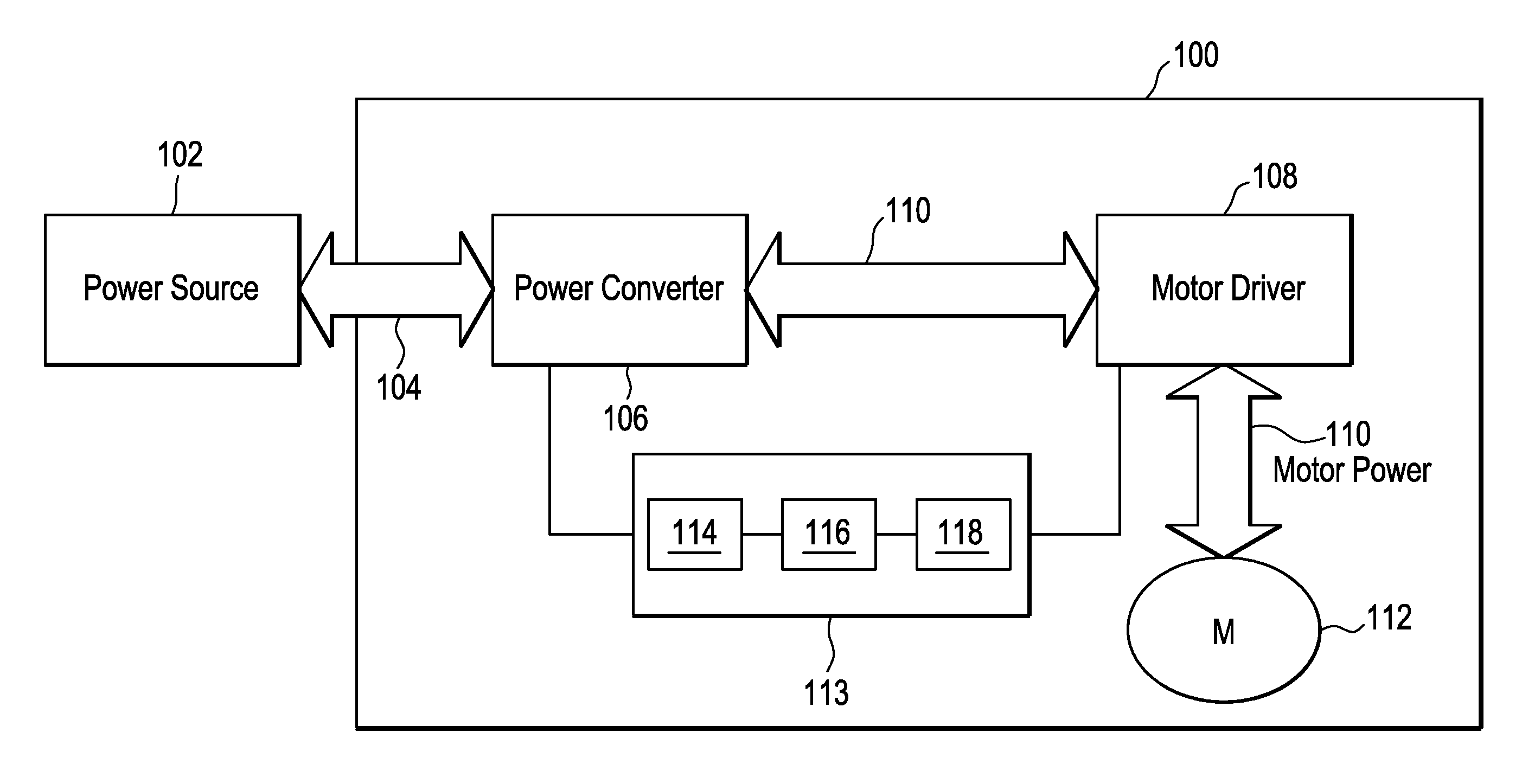
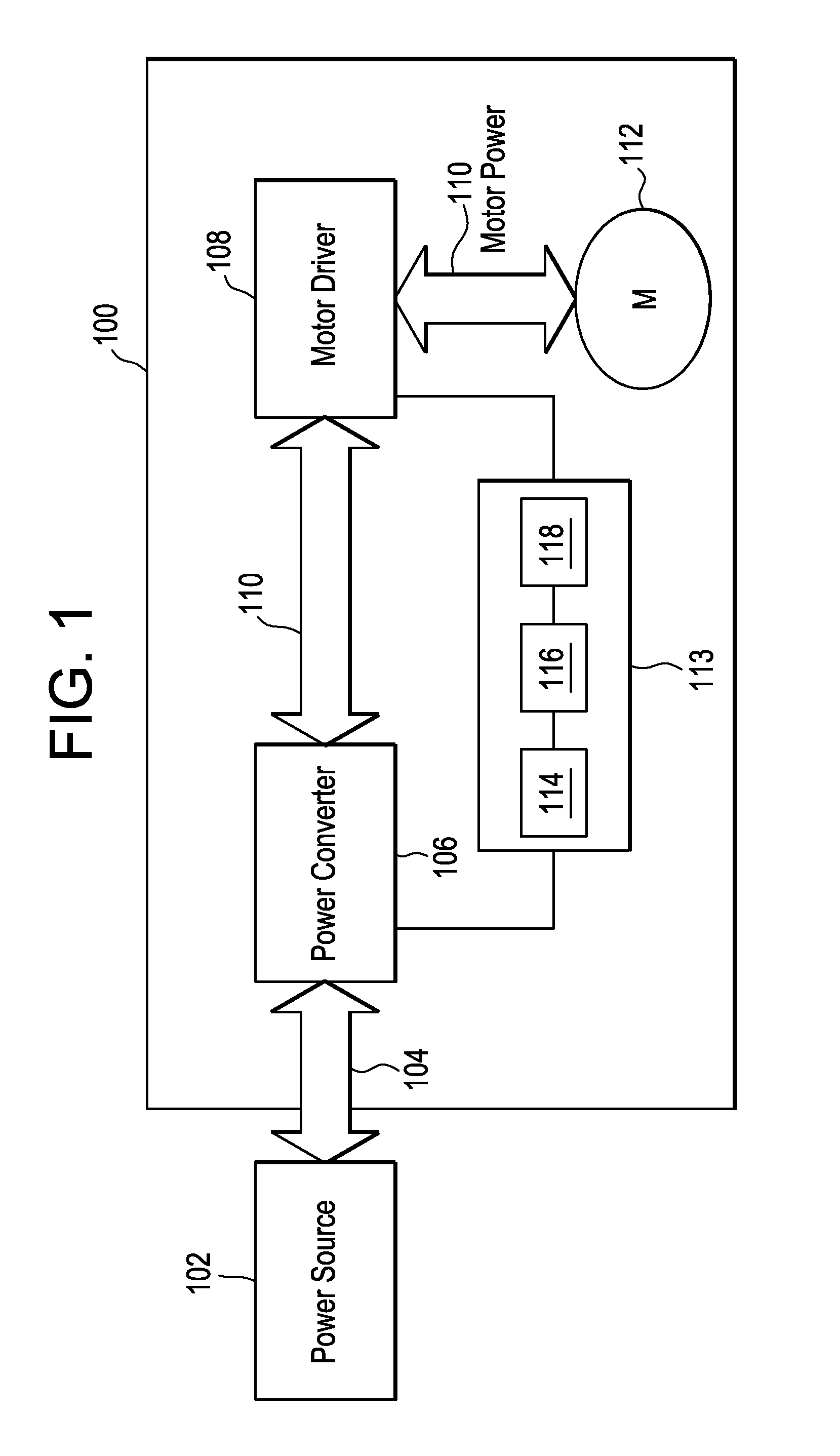
[0016]FIG. 1 shows a block diagram of a motor control system 100 according to one embodiment of the present invention. The motor control system 100 is shown coupled to a power source 102.

[0017]The system 100 may be, for example, a motion system for an electric excavator. Of course the teachings herein may be applied to any motor control system (with or without a power converter) where a power-limiting interface may be needed for operation.

[0018]The power source 102 may be any type of power source that provides electrical power. For example, the power source 102 may be a battery. The power source 102 could also be any AC power source including, but not limited to, a power generation plant or a sub-station connected thereto. The power source 102 may produce, in one embodiment, 3-phase AC power.

[0019]The power source 102 is coupled to the system 100 by transmission system 104. The transmission system 104 may include a transformer to convert the power to a desired level.

[0020]The system...


PUM


Abstract

A motor control system for controlling two or more motor groups includes a power converter that receives power from a power source and converts the power to an intermediate power and an intermediate power link coupled to the power converter. The motor control system also includes at least one motor driver coupled to the intermediate power link configured to provide power to one or more motors and a controller coupled to the power converter and the at least one motor driver. The controller is configured to cause the at least one motor driver to limit the amount of power delivered to the one or more motors based on the amount of power that the power converter can produce.

Description

BACKGROUND OF THE INVENTION[0001]The subject matter disclosed herein relates to motor control and, in particular, to controlling multiple motors in a multi-motion system during times of reduced power or grid fluctuation.[0002]A typical motor control system includes a power converter that converts power from a power source (typically after being stepped down by a transformer) into an intermediate form and provides it to an intermediate link. A motor driver utilizes the power from the intermediate link to control, for example, the operation of an electric motor. In particular, the motor driver (typically implemented as an inverter or chopper) transforms the fixed voltage or current source or link power to a variable frequency and magnitude voltage or current for supply to a motor driving a load.[0003]The power flow from or to the power source is limited by factors such as the impedance between the power source and the power converter, the voltage of the power source during operation, ...

Claims


Application Information

Patent Timeline
IPC IPC(8): H02P7/00
CPCH02P5/00H02P5/68
Inventor RAMAMURTHY, SHYAM SUNDERJACKSON, TIMOTHY RAYWHALEN, JR., RICHARD FRANCIS
Owner GENERAL ELECTRIC CO
Why Eureka
Try Eureka