Eureka AIR delivers breakthrough ideas for toughest innovation challenges, trusted by R&D personnel around the world.

Method for determining fuel blend in a dual fuel mixture

a dual fuel mixture and fuel blend technology, applied in the direction of electrical control, process and machine control, instruments, etc., can solve the problems of increased oil dilution, increased difficulty in cold starting of the motor, and increased oil dilution, so as to achieve optimal engine operation

Active Publication Date: 2016-02-18
VOLVO LASTVAGNAR AB
View PDF3 Cites 6 Cited by
  • Summary
  • Abstract
  • Description
  • Claims
  • Application Information

AI Technical Summary

Benefits of technology

The present invention provides a method for real-time estimation of the fuel blend in a dual fuel mixture, allowing for optimal engine operation for any blend in the mixture. Biodiesel can be blended with petroleum diesel at any concentration, and its use may have advantages such as reducing emissions and need for recalibration, but also presents challenges such as increased oil dilution and increased NOx emissions. The method provides an accurate estimate of the biodiesel content of the fuel and optimizes fuel consumption and power output based on the fuel blend.

Problems solved by technology

However, the use of biodiesel may incur problems; for example with biodiesel fuel, cold start of the motor may be more difficult, especially at low temperatures, with respect to conventional diesel.
A further problem is given by increased oil dilution due to the evaporation properties of biodiesel.
While the materials compatibility challenges have largely been met in “flexi-fuel” vehicles, the engine and after-treatment operation has not been optimized as a function of fuel type (i.e. ethanol, bio diesel, etc.).
Reducing NOx produced from engines running on biodiesel is a challenging task to be able to meet the emission requirements.
Hence, a further problem is to provide an accurate estimate the RME content of the fuel to optimize both the fuel consumption information of the engine and the torque produced by the engine.
This model is not directly applicable on other engine models.

Method used


Image

  • Method for determining fuel blend in a dual fuel mixture
  • Method for determining fuel blend in a dual fuel mixture
  • Method for determining fuel blend in a dual fuel mixture

Examples


Embodiment Construction

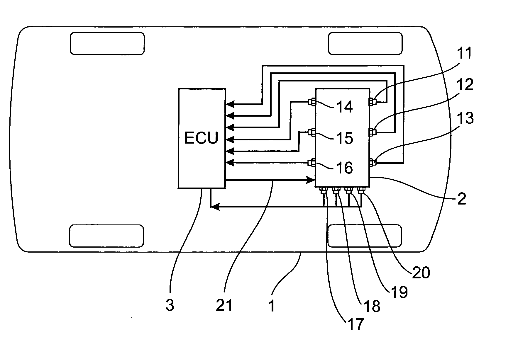
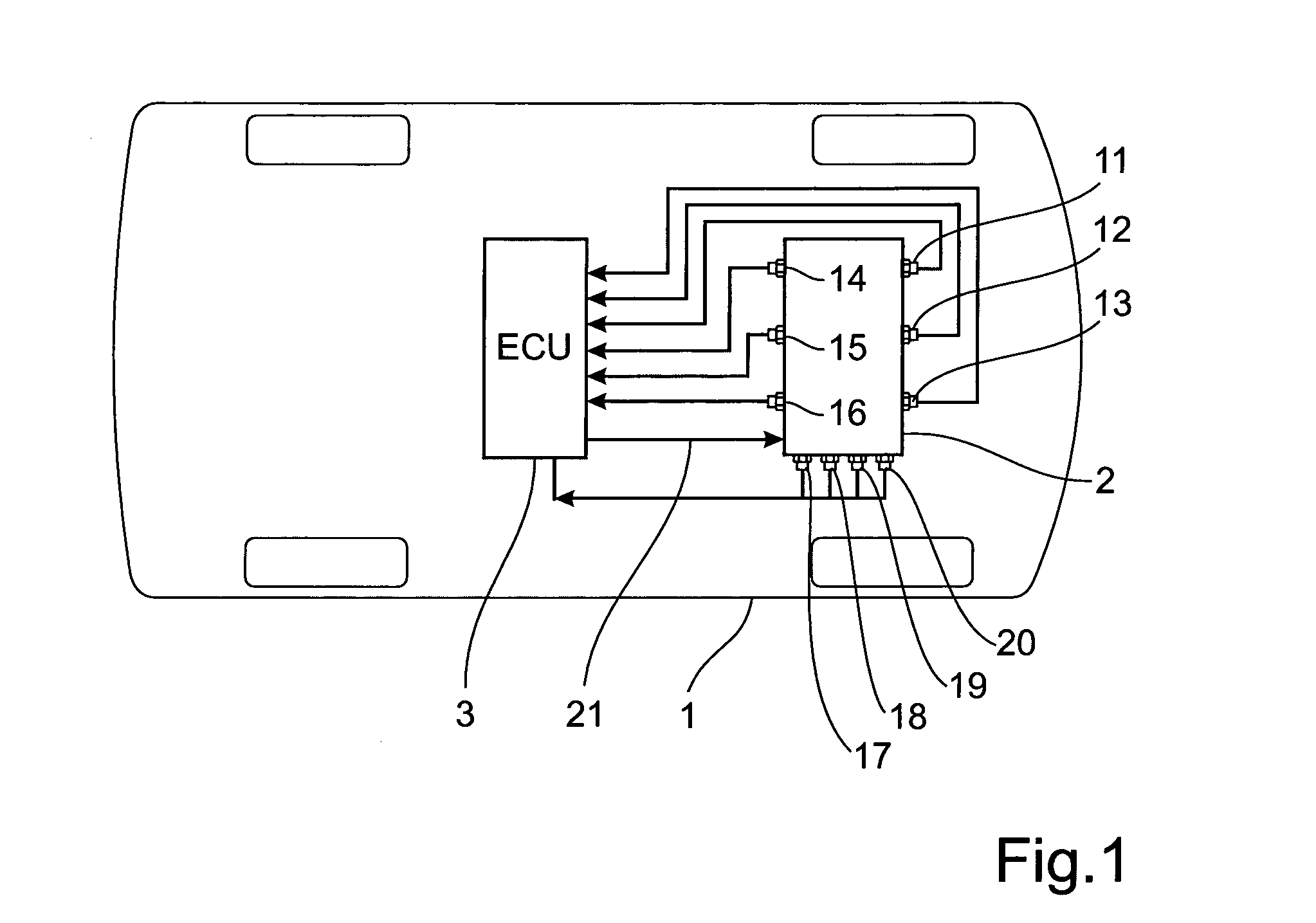
[0061]In future fuels a promising candidate for most diesel engines will include bio-diesel, or RME. The example studied here is RME, mixed in proportions 7%, 50% and 100% in diesel oil (VSD10). A 13 litre Euro V engine has been used as test object. In order to get a cost efficient detection of which blend of fuel the vehicle is filled with, e.g. the % content of bio-diesel, a combination of soft sensors is used. By analysing the different influences on the engine at 7% and 100% RME a number of engine related parameters that could be measured by available sensors were listed (Table 1).

TABLE 1Measured variablesNo.VariableIDUnit1TorquemdNm2Exhaust manifoldACM.se_EngExhTemp° C.temperature3Engine speedAPS_EngineSpeed_TSrpm4Exhaust manifold pressureExhaustManifoldPressurekPa5EGR mass flowmfv_EgrMassFlowValidatedkg / s6Fuel Injection parameter 1rpc_Ipartmg / str7Fuel Injection parameter 2rpc_MpropFlowDemandmg / str8Fuel Injection parameter 3rpe_RailPressurebar9Boost pressurese_BoostPreskPa10Boo...


PUM


Abstract

A method is provided for determining fuel blend in a dual fuel mixture including a first and a second fuel in an internal combustion engine. The method includes the steps of measuring multiple engine parameters using sensors during transient cycle operation for a predetermined range of engine loads and fuel blends; using system identification of transient time series of the measurements to determine one or more relevant engine parameters; determining a model for estimation of the fuel blend based on said one or more engine parameters; using the model fur determining a current fuel blend during transient operation using current measured values of the one or more engine parameters, and using the calculated current fuel blend for controlling the amount of dual fuel mixture injected into each cylinder of the internal combustion engine. A vehicle and a computer program product using the method are also provided.

Description

BACKGROUND AND SUMMARY[0001]The present invention relates to a method for determining fuel blend in a dual fuel mixture. The method allows for real-time estimation of the fuel blend in a fuel having variable fuel and combustion properties depending on the blend, providing optimal engine operation for any blend in the dual fuel mixture.[0002]Biodiesel can be used in pure form or may be blended with petroleum diesel at any concentration in modern diesel engines. The use of biodiesel will increase in the future especially due to the advantages of such type of fuel. In particular using biodiesel has the effect of a particulate reduction up to 80%. Furthermore, biodiesel gives the possibility of recalibrating the Soot-NOx trade-off in order to eliminate increase of NOx. Also it gives the possibility of reducing the regeneration frequency of the diesel particulate filter. However, the use of biodiesel may incur problems; for example with biodiesel fuel, cold start of the motor may be more...

Claims


Application Information

Patent Timeline
IPC IPC(8): F02D41/00F02D41/26
CPCF02D41/26F02D41/0027F02D41/0072F02D41/1405F02D41/1446F02D41/1448F02D41/2432F02B37/24F02D41/0007F02D41/0025F02D2041/1409F02D2041/1423F02D2200/021F02D2200/0406F02D2200/0414F02D2200/0612F02D2200/101F02D19/088Y02T10/30F02D19/08F02D19/087F02D19/084F02D19/085
Inventor AHLINDER, SVEN
Owner VOLVO LASTVAGNAR AB
Why Eureka
Eureka Blog
Learn More