Motor control apparatus

a technology of motor control and control apparatus, which is applied in the direction of electric controllers, dynamo-electric converter control, instruments, etc., can solve the problems of inability to know the position, the available power of the motor, and the inability to appropriately control the motor power, so as to prevent excessive reduction of the available power of the electric motor

Inactive Publication Date: 2011-05-31
HONDA MOTOR CO LTD
View PDF13 Cites 3 Cited by
  • Summary
  • Abstract
  • Description
  • Claims
  • Application Information

AI Technical Summary

Benefits of technology

The present invention is conceived in view of the above circumstances, and has an object to provide a motor control apparatus which can control motor power appropriately even if a sensor which detects a phase position does not work.
According to the motor control apparatus of the first aspect, even in a case in which a detection value of the phase position cannot be obtained when the phase position sensor does not work, the phase alternation device can set the phase position alternatively as either the maximum value or the minimum value in the phase variable area. Therefore, motor power can be controlled in accordance with the phase position which is set alternatively as the maximum value or the minimum value in the phase variable area. As a result, an available power of the electric motor can be prevented from being reduced excessively; thereby ensuring a prescribed amount of power.
In this case, for example, inappropriate actions such as an excessive increase in the motor torque, a vibration, and the like can be prevented by setting a torque instruction value of the electric motor to zero immediately after detecting a failure of the phase position sensor.
According to the motor control apparatus of the second aspect, even in a case in which a detection value of the phase position cannot be obtained when the phase position sensor does not work, the phase alternation device can set the phase position alternatively as either the maximum value or the minimum value in the phase variable area. Therefore, motor power can be controlled in accordance with the phase position which is set alternatively as the maximum value or the minimum value in the phase variable area. As a result, an available power of the electric motor can be prevented from being reduced excessively; thereby ensuring a prescribed amount of power.
According to the motor control apparatus of the third aspect, even in a case in which a detection value of the phase position cannot be obtained when the phase position sensor does not work, the phase alternation device can set the phase position alternatively as either the maximum value or the minimum value in the phase variable area. Therefore, motor power can be controlled in accordance with the phase position which is set alternatively as the maximum value or the minimum value in the phase variable area. As a result, an available power of the electric motor can be prevented from being reduced excessively; thereby ensuring a prescribed amount of power.
Furthermore, the phase position is set alternatively as the maximum value or the minimum value in the phase variable area in accordance with a rotation property of a vehicle (for example, rotational speed of a drive shaft). For example, when the rotational speed of the drive shaft is relatively fast, the phase position is set to a position of field weakening; when the rotational speed of the drive shaft is relatively slow, the phase position is set to a position of field forcing. Therefore, a prescribed amount of power can be appropriately ensured.

Problems solved by technology

In the motor according to the above conventional art, there is a concern that motor power cannot be appropriately controlled if a sensor which detects a phase position does not work, in a case in which the motor power is controlled in accordance with a detection value of the sensor.
As a result, the available power of the motor according to the phase position cannot be known, and the available power which can be controlled is excessively decreased.
Therefore, desired amount of power cannot be maintained.

Method used


Image

  • Motor control apparatus
  • Motor control apparatus
  • Motor control apparatus

Examples


Embodiment Construction

An embodiment of a motor control apparatus of the present invention will be described below with reference to the drawings.

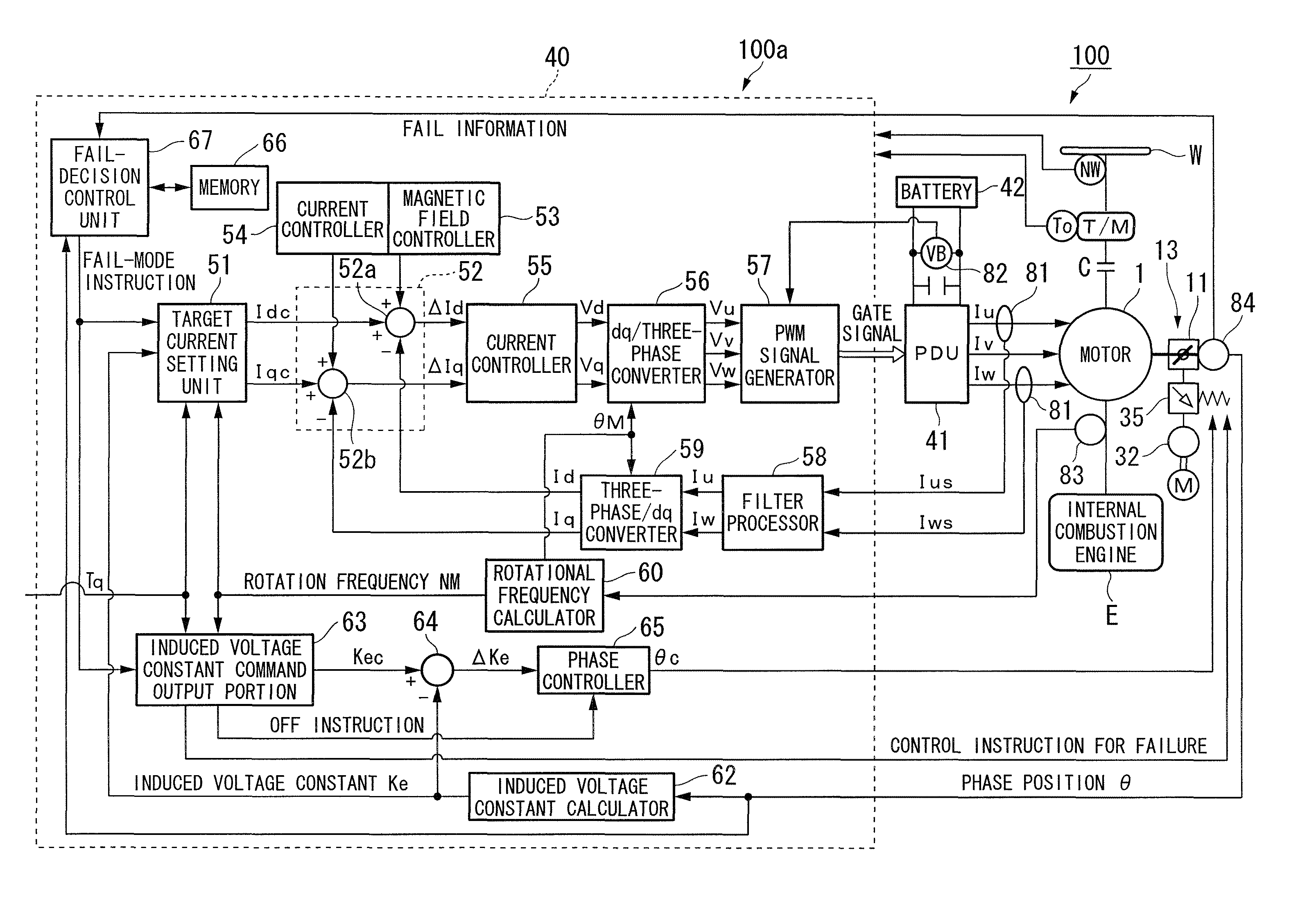
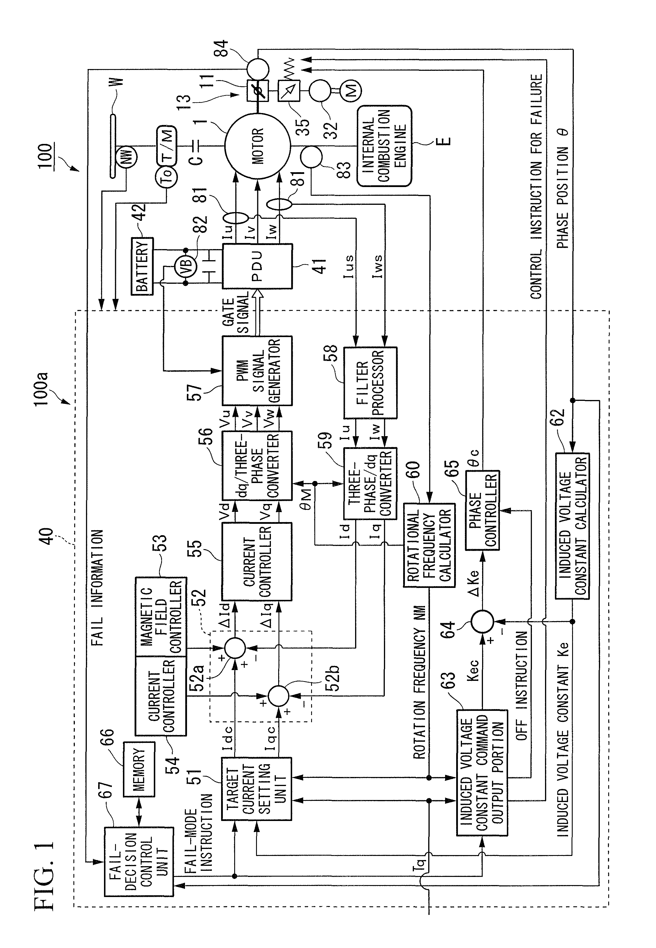
The motor control apparatus of the present embodiment is mounted as a controller in a vehicle such as a hybrid vehicle or an electric vehicle that is provided with a motor as the traveling driving device. Specifically, as shown in FIG. 1, a vehicle 100 that is mounted with a motor control apparatus 100a (hereinafter, “control apparatus 100a”), is a parallel hybrid vehicle that is provided with a motor 1 and an internal combustion engine E as driving sources. The motor 1, the internal combustion engine E and a transmission T / M are connected in series, and at least the drive force of the motor 1 or the internal combustion engine E is transmitted to driving wheels W of the vehicle 100 via a clutch C and the transmission T / M.

When drive force is transmitted from the driving wheels W side to the motor 1 during deceleration of the vehicle 100, the motor 1, by functioni...


PUM


Abstract

A motor control apparatus includes: an electric motor having an outer rotor and an inner rotor which can alter mutual relative phases; a phase alternation device which alters the relative phase; a phase position sensor which detects a phase position with respect to the relative phase; and a fail-decision control unit which sets the relative phase as a maximum value or a minimum value (that is, a most forcing phase and a most weakening phase) in a phase variable area of the phase alternation device in accordance with a rotation number of the electric motor when the phase position sensor does not work.

Description

TECHNICAL FIELDThe present invention is relates to a motor control apparatus.Priority is claimed on Japanese Patent Application No. 2007-151672, filed Jun. 7, 2007, the content of which is incorporated herein by reference.BACKGROUND OF THE INVENTIONConventionally, a permanent magnet rotational electric motor is known in which there are provided a first rotor and a second rotor that are provided concentrically around an axis of rotation of an electric motor, and the relative positions in the circumferential direction of the first rotor and the second rotor, namely, the phase difference thereof are controlled in accordance with the rotational speed of the rotational electric motor, or in accordance with the speed of a rotating magnetic field that is generated in a stator (see, for example, Japanese Unexamined Patent Application, First Publication No. 2002-204541).In addition, conventionally, a motor is known in which there are provided a first permanent magnetic pole piece and a secon...

Claims


Application Information

Patent Timeline
Patent Type & Authority Patents(United States)
IPC IPC(8): G05B9/02H02K16/02H02K21/14H02P21/00H02P21/06H02P21/22H02P27/04H02P27/08
CPCH02K11/001H02K21/029H02P21/0089H02P29/02H02P31/00H02P21/06H02P2207/03H02K11/20
Inventor FUJISHIRO, NAOKI
Owner HONDA MOTOR CO LTD
Why Eureka
Try Eureka