
Condensation particle counter false count performance

a technology of condensation particle counter and false count, which is applied in the field of condensation particle counter false count performance, can solve the problems of condensation particle counter, inability to reduce or eliminate particle counts using these techniques, and the reported count rate of contemporaneous water-based condensation particle counters (cpcs) is generally not acceptable for clean room applications

Active Publication Date: 2019-12-31
TSI INC
View PDF55 Cites 1 Cited by
  • Summary
  • Abstract
  • Description
  • Claims
  • Application Information

AI Technical Summary

Problems solved by technology

However, as volumetric sample flow rates increase, any working fluid that drains in to the flow path has a tendency to create bubbles which then grow in to large particles that gets detected by an optical sensor within the CPC.
However, none of these techniques needs to be applied to reducing or eliminating particle counts as a single technique.
Reported count rates in contemporaneous water-based condensation particle counters (CPCs) are generally not acceptable for clean room applications due to the false-particle count rate.
The science of condensation particle counters, and the complexity of the instrumentation, lies with the technique to condense vapor onto the particles.
Water has very high vapor diffusivity, so a laminar flow water-based CPC with a cool condensation region does not work thermodynamically.
In general, the liquid purity is not as tightly controlled for water as for alcohols purchased from chemical supply houses.
The impurities in the water may build up in the “wick” (described below), and eventually cause the wick material to become ineffective.
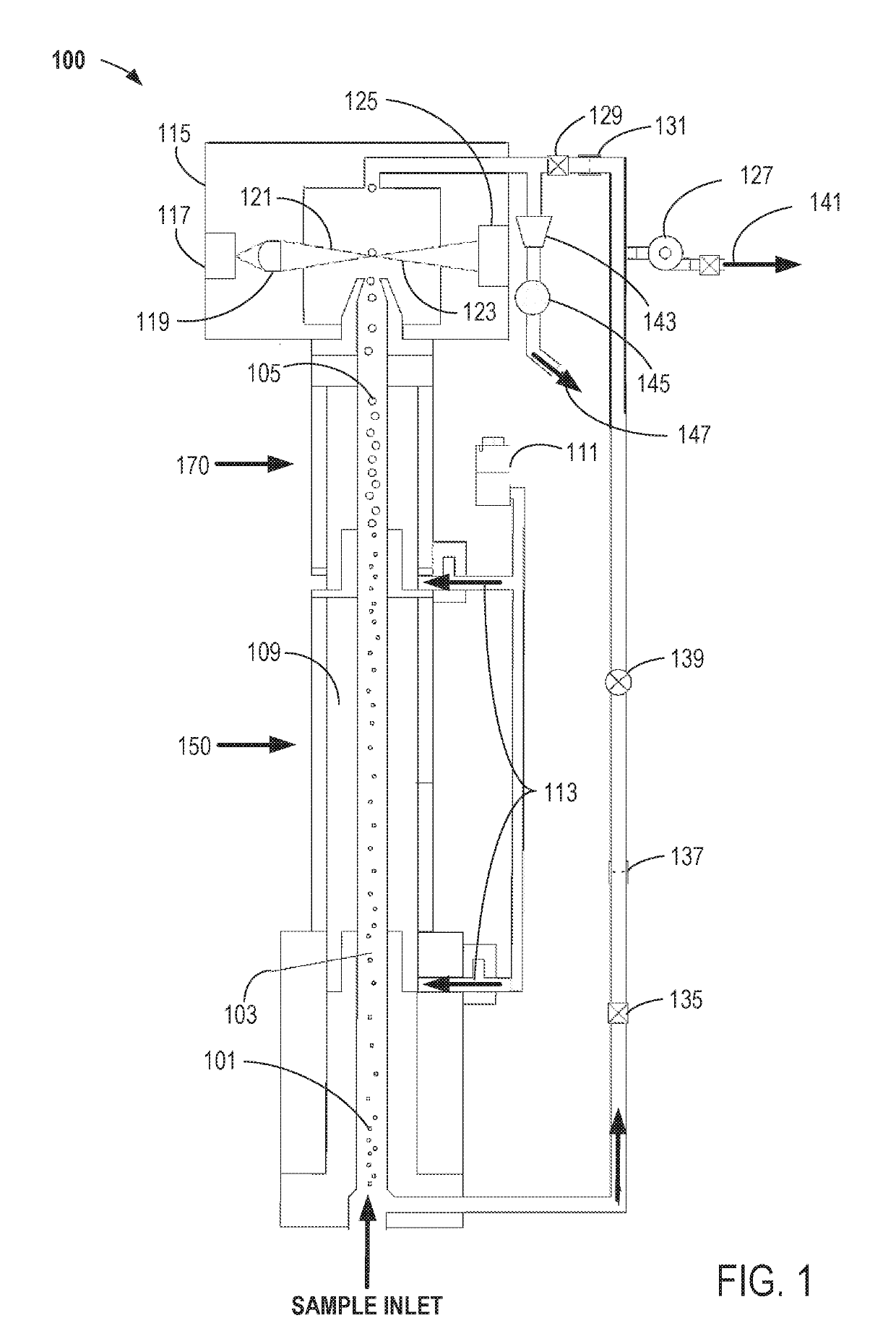
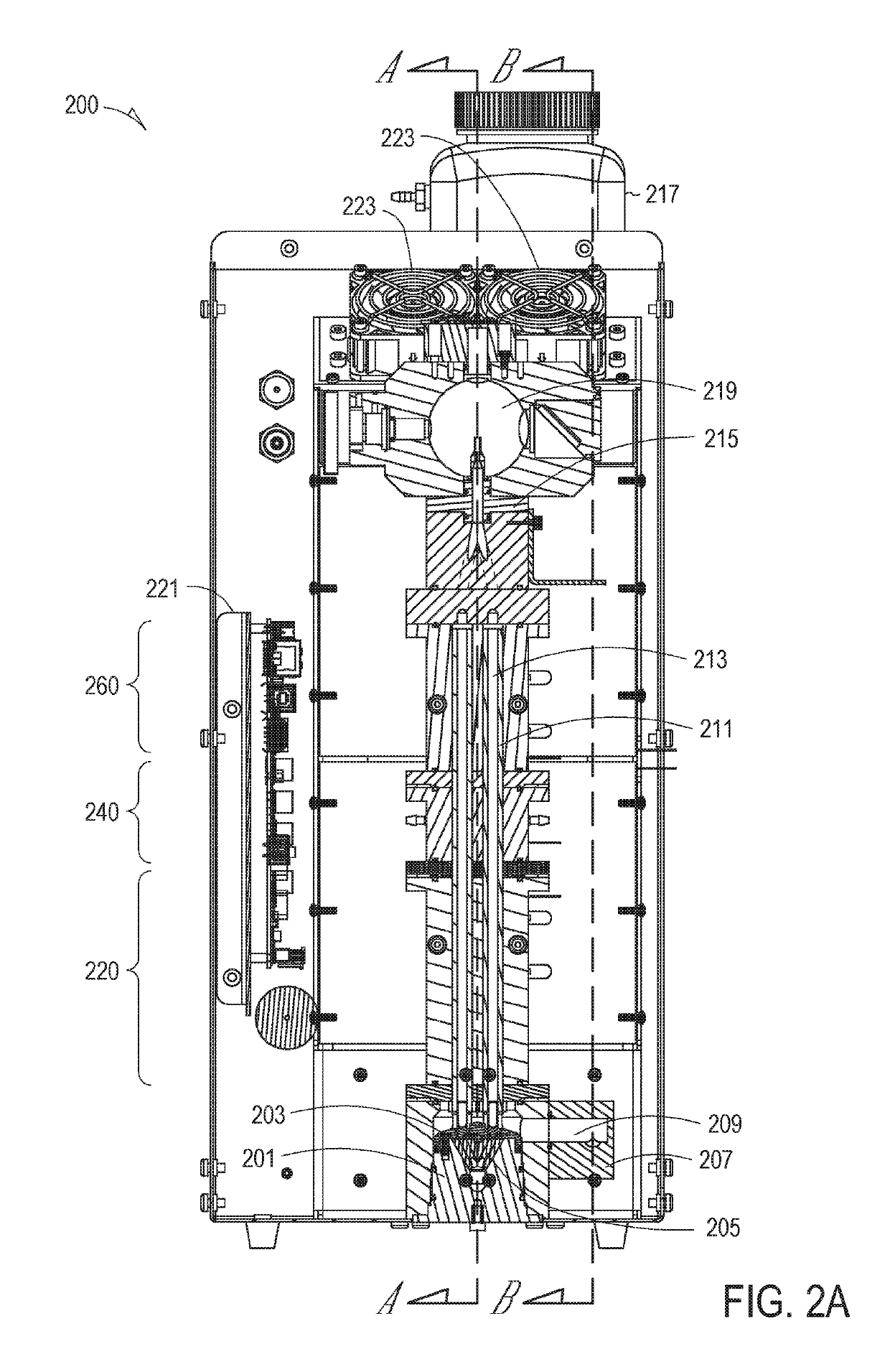
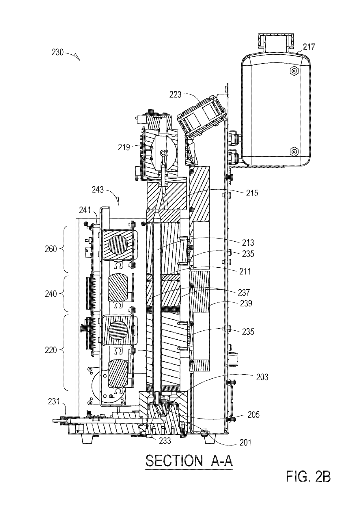
However, either an excess volume of water, or water provided to the wicks 211 too rapidly (e.g., when supplied in “spurts”), can contribute to the formation of either water bubbles or empty droplets not containing any particles.
Either of these conditions can lead to an increase in false-particle counts.

Method used


Image

  • Condensation particle counter false count performance
  • Condensation particle counter false count performance
  • Condensation particle counter false count performance

Examples


Embodiment Construction

[0010]The description that follows includes illustrative examples, devices, and apparatuses that embody the disclosed subject matter. In the following description, for purposes of explanation, numerous specific details are set forth in order to provide an understanding of various embodiments of the inventive subject matter. It will be evident, however, to those of ordinary skill in the art that various embodiments of the inventive subject matter may be practiced without these specific details. Further, well-known structures, materials, and techniques have not been shown in detail, so as not to obscure the various illustrated embodiments.

[0011]As used herein, the term “or” may be construed in an inclusive or exclusive sense. Additionally, although various exemplary embodiments discussed below focus on particular ways to reduce false-particle counts by eliminating empty water droplets or bubbles being counted as actual particles, other embodiments consider electronic filtering techniq...


PUM

PropertyMeasurementUnit
angleaaaaaaaaaa
angleaaaaaaaaaa
lengthaaaaaaaaaa

Abstract

Various embodiments include methods of reducing false-particle counts in a water-based condensation particle counter (CPC). One embodiment of a method includes delivering water into one or more wicks, sensing an excess volume of water delivered to the wicks, collecting the excess volume of water into a collection reservoir, and draining the excess volume of water from the collection reservoir. Other methods and apparatuses are disclosed.

Description

CLAIM OF PRIORITY[0001]This Patent Application is a U.S. National Stage Filing under U.S.C. § 371 from International Application Serial Number PCT / US2016 / 019083, filed on Feb. 23, 2016, and published as WO 2016 / 137962 on Sep. 1, 2016, which Patent Application claims the benefit of priority to U.S. Provisional Patent Application Ser. No. 62 / 119,558, filed on Feb. 23, 2015, which applications are hereby incorporated by reference in their entireties.BACKGROUND[0002]Condensation Particle Counters (CPCs) have different mechanisms to drain the working fluid out of the growth tube or wick. Most contemporary CPCs rely on gravity to drain the working fluid. However, as volumetric sample flow rates increase, any working fluid that drains in to the flow path has a tendency to create bubbles which then grow in to large particles that gets detected by an optical sensor within the CPC. Since these counts are generated internally to the CPC and are not caused by actual particles from a monitored e...

Claims


Application Information

Patent Timeline
Patent Type & Authority Patents(United States)
IPC IPC(8): G01N15/06
CPCG01N15/065G01N2015/0693G01N21/85
Inventor AVULA, SREENATHREMIARZ, RICHARDCHANCELLOR, GEORGE JOHNANDERSON, TYLERBJORKQUIST, DANIEL C.CALDOW, ROBERTMORELL, SEANQUANT, FREDERICK R.HERING, SUSANNE V.LEWIS, GREGORY S.
Owner TSI INC
Learn More