
Time base correction method for high accuracy sampling scope-based measurements

a time base correction and high-accuracy technology, applied in electromagnetic transmission, instruments, transmission, etc., can solve the problems of generation of high frequency quadrature signals, insufficient time base accuracy obtained, and considerable attention to time base accuracy

Active Publication Date: 2020-01-14
GUZIK TECHN ENTERPRISES
View PDF7 Cites 2 Cited by
  • Summary
  • Abstract
  • Description
  • Claims
  • Application Information

AI Technical Summary

Benefits of technology

The patent describes a way to measure signals that have a repeating pattern. The method uses a sampling scope to measure the signals and a reference sine wave signal that is also measured. These signals are synchronized with a common trigger signal. The result is that the method reduces errors caused by the time base, which is the time between when the signals are measured. The technical effect of this method is to provide more accurate measurements for signals with a repeating pattern.

Problems solved by technology

However, in most practical applications, time base accuracy obtained may be insufficient for needed precision measurements due to device changes after initial factory calibration, variations of ambient temperature and other factors.
The problem of time base accuracy has attracted considerable attention in prior art publications.
However, the described methods have a number of disadvantages.
They require a generation of high frequency quadrature signals, which is complicated.
Moreover, time base calibration using laser diodes requires a sophisticated electro-optical setup and generally can only be done in a dedicated facility.
Also, these calibration methods are based on a complicated numerical orthogonal distance regression method, which may not produce satisfactory results in all cases as indicated in the above-cited references.
Time base error is calculated from multiple sets of data using a maximum-likelihood estimator based on an iterative numerical procedure which may be affected by convergence and numerical instability problems.

Method used


Image

  • Time base correction method for high accuracy sampling scope-based measurements
  • Time base correction method for high accuracy sampling scope-based measurements
  • Time base correction method for high accuracy sampling scope-based measurements

Examples


Embodiment Construction

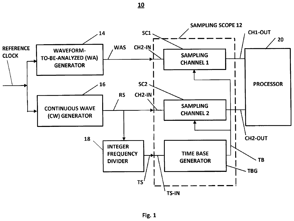
[0038]Time base distortion varies over time and depends on a number of factors, such as a sampling rate of a signal-to-be-analyzed, acquisition time for such a signal, ambient temperature and others. In view of these factors, in accordance with a form of the invention, measurement system 10, illustrated in FIG. 1, a time base distortion measurement for a signal-to-be-analyzed is performed using a 2-channel sampling oscilloscope (or scope) 12. In an exemplary form, the 2-channel sampling scope 12 includes two sampling channels, sampling channel 1 (SC1), having an input CH1-IN and an output CH1-OUT, a sampling channel 2 (SC2), having an input CH2-IN and an output CH2-OUT, and a time base generator TBG, providing sampling signal TB to inputs of the respective sampling channels SC1 and SC2. The time base generator TB includes a trigger signal input TS-IN for receiving an applied trigger signal TS. In the illustrated form, a common reference clock characterized by a repetition period Tw,...


PUM


Abstract

A method and apparatus for resolving time base-generated errors from sampling scope-based measurements. Mutually synchronized repetitive waveform-to-be-analyzed signals (WAS) and repetitive sinusoidal reference signals (RS) are respectively applied to a first channel and a second channel of a sampling scope. A time base generator applies a sampling signal to the first and second channels. An average sine wave period Tav for k samples of RS is determined, followed by determination of phase error φk for each of the k samples, corresponding to phase differences between an ideal sine wave signal and the applied reference sinusoidal signal. Time base error values dk for k samples are calculated from dk=φk*Tav / 2π. Error values dk correct time base errors in the sampling signal, and the WAS is re-sampled at sampling times adjusted by dk.

Description

TECHNICAL FIELD[0001]The present disclosure relates to the correction of accuracy-degrading time base distortions which occur in sampling oscilloscope (or “scope”)-based measurements, where the distortions are due to imperfections of time base generation circuitry in the scope.BACKGROUND[0002]Sampling scopes, or equivalent time, scopes are used for acquisition of repetitive high frequency signals. The advantages of sampling scopes, as compared to real-time digitizers, are based on the fact that signal samples are taken at a relatively low sampling rate and the signal is acquired during multiple signal repetitions, so that each signal sample is taken with a varied delay relative to a trigger signal. This “equivalent time” sampling method allows high dynamic range and bandwidth which are essential for high frequency measurements (e.g., for use in optical and communications applications). For example, modern sampling scopes offer 16-bit sampling analog-to-digital (ADC) resolution with ...

Claims


Application Information

Patent Timeline
IPC IPC(8): G01D18/00G01D21/00G01P21/00H04B10/079G01R13/02G01R35/00
CPCG01R13/0272H04B10/0795
Inventor STEIN, ANATOLI B.TARATORIN, ALEXANDERSEREBRYANSKIY, VALERIY
Owner GUZIK TECHN ENTERPRISES
Learn More