Convertible tool case to a stepstool

a tool case and step stool technology, applied in the field of position adjustable support assembly, can solve the problems that the fixed extension provides limited versatility for supporting various items, and achieve the effects of improving attachment and retention, enhancing attachment to the horizontal member, and more ductil

Active Publication Date: 2020-01-28
BLAKE JAMES FRANCIS
View PDF50 Cites 2 Cited by
  • Summary
  • Abstract
  • Description
  • Claims
  • Application Information

AI Technical Summary

Benefits of technology

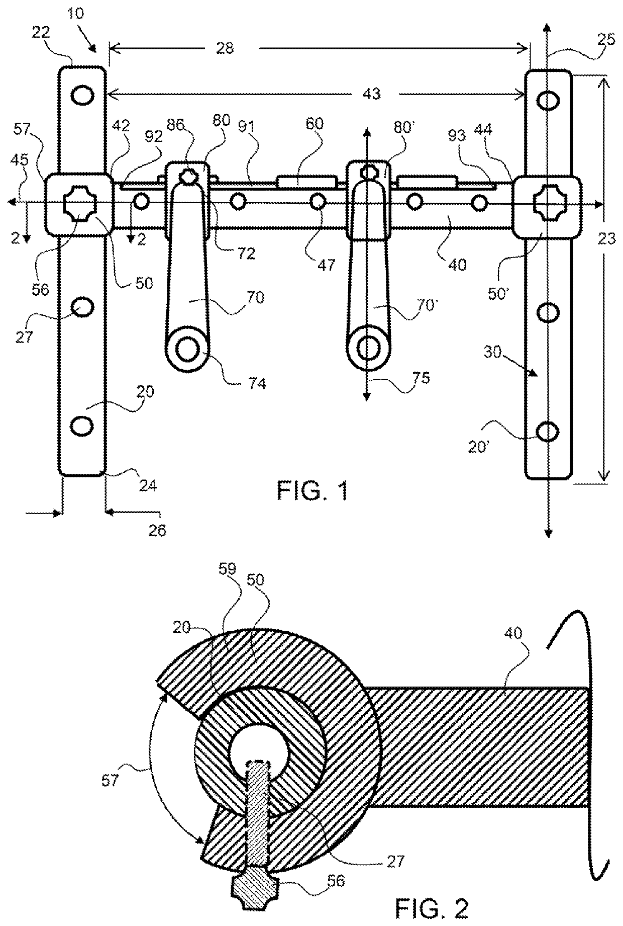
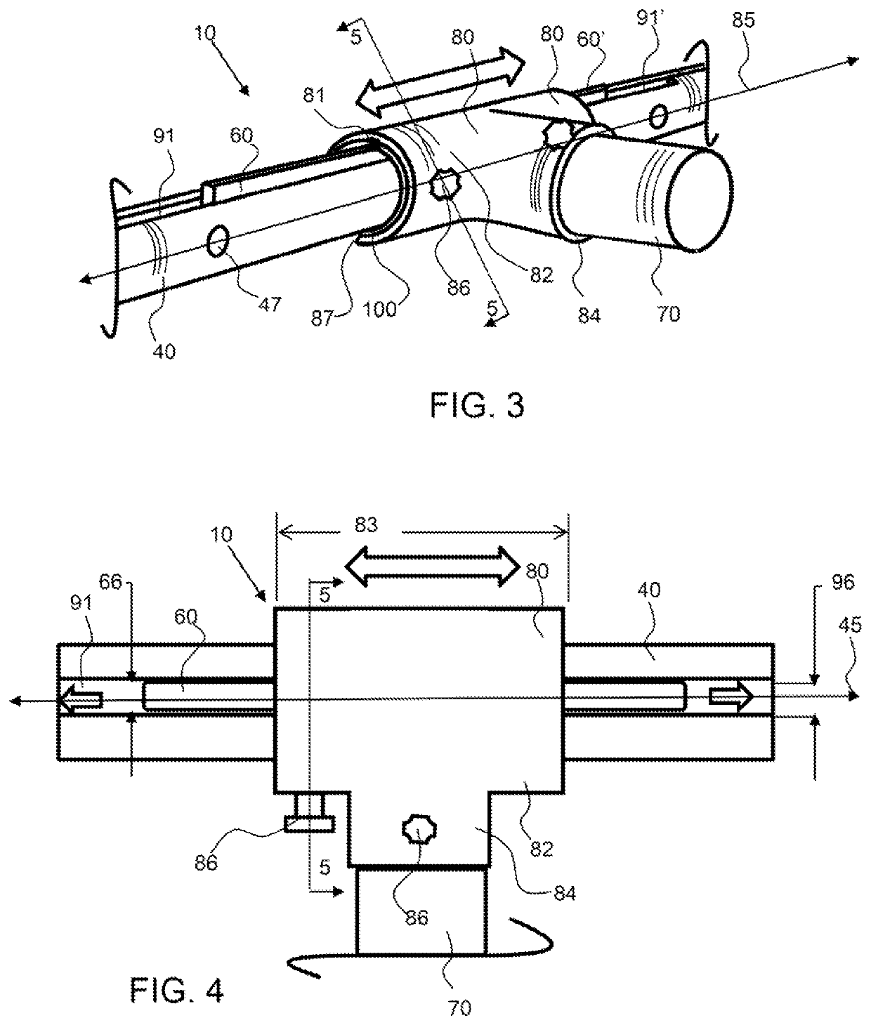
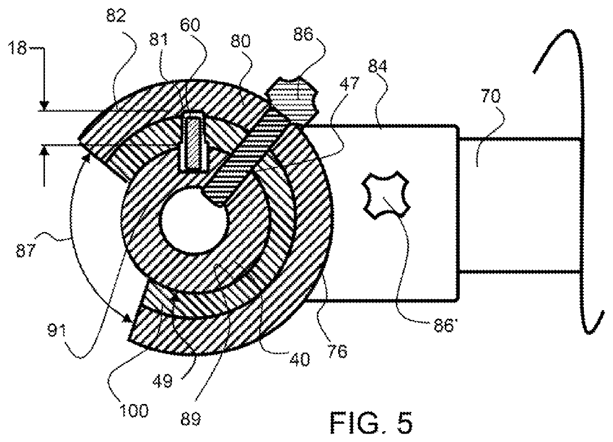
[0006]A gap between the fins may be large enough to allow an extension attachment to be snapped onto and attached to the horizontal attachment between the fins or between a fin and a vertical support member or a horizontal attachment between a horizontal support member and the vertical support member. The extension attachment may then be slid over a fin, or a fin may be slid along the fin slot into the extension attachment. An extension attachment may have an inner retainer that enhances the attachment to the horizontal member. For example, a sleeve may be inserted into the inner portion of the support coupler to improve the attachment and retention of the extension attachment to the horizontal support member. The inner retainer may be made from a material that is has different properties than the rest of the extension couple, such as being more ductile or alternatively stiffer. For example, the inner retainer may be CPVC and the rest of the extension coupler may be PVC. Poly vinyl chloride (PVC) is a thermoplastic polymer, while CPVC is a thermoplastic produced by the chlorination of the PVC resin. CPVC is significantly more ductile than PVC, thereby allowing greater flexure and crush resistance.
[0012]The receivers of the base and / or the top may be channels for receiving the second end and first end, respectively, of the vertical support members. The receivers may have an aperture for receiving a retainer, such as a pin, as described herein. The receivers may have automatic attachment means, wherein upon insertion, the vertical support member is locked or attached and will not be released until a release lever or feature is activated. A receiver may be or comprise a latch, such as a spring loaded latch or a living hinge latch. A receiver may comprise a cylinder having a gap opening for receiving the vertical support member. The vertical support member or members, such as the left-extended and / or right extended vertical support members, may be rotated into the gap opening of the latch and snapped into the latch for attachment. An enlarged portion of the vertical support member may prevent the vertical support member from sliding out of the latch when the tool case is moved or lifted. Likewise, the left-side and right-side vertical support members of the center assembly may be snapped into a gap opening of a latch type receiver.
[0015]A top-step retainer assembly may be coupled to the base by a pair of rails that slide into rail apertures within the base. The top-step retainer assembly may have leg receivers, such as a conduit to receive the extended end of the leg. The extended end of the leg, which may be a rod, may fit within the cylindrical leg receiver to provide secure retention of the leg with the top-step retainer assembly. Note that the leg may fit around a post, wherein the leg is a cylinder having an open extended end and the leg receiver is a rod or post that extends into the extended end of the leg. A top-step retainer assembly may also comprise additional support elements, such as support flanges that extend to provide more stability to the step stool. In an exemplary embodiment, the support flanges are rotatably connected to the top-step retainer assembly and may be rotated forward to provide additional support to prevent the stepstool from falling forward over the top-step.
[0017]A method of converting a tool case to a stepstool may be quick and easy. The top-step retainer assembly may be positioned, such as by pulling it out from the base. The top cover lid may be removed to expose the top-step legs. The top-step legs may be rotated out from the cover to an extended position. The top cover may be rotated over or otherwise configured with the legs aligned with the top-step retainer assembly. The legs may be retained in the leg receivers of the top-step retainer assembly to convert the tool case to a stepstool.

Problems solved by technology

Since the types of items to be supported range is sized and shape, the fixed extensions provide limited versatility for supporting various items.

Method used


Image

  • Convertible tool case to a stepstool
  • Convertible tool case to a stepstool
  • Convertible tool case to a stepstool

Examples


Embodiment Construction

[0039]As used herein, the terms “comprises,”“comprising,”“includes,”“including,”“has,”“having” or any other variation thereof, are intended to cover a non-exclusive inclusion. For example, a process, method, article, or apparatus that comprises a list of elements is not necessarily limited to only those elements but may include other elements not expressly listed or inherent to such process, method, article, or apparatus. Also, use of “a” or “an” are employed to describe elements and components described herein. This is done merely for convenience and to give a general sense of the scope of the invention. This description should be read to include one or at least one and the singular also includes the plural unless it is obvious that it is meant otherwise.

[0040]Certain exemplary embodiments of the present invention are described herein and are illustrated in the accompanying figures. The embodiments described are only for purposes of illustrating the present invention and should not...


PUM


Abstract

A position adjustable support assembly is convertible from a tool case, to a step stool. A segmented position adjustable support assembly has a center assembly and a left and right assembly. The left and right assemblies are rotatable about the center assembly and the vertical supports of the center, left and right assemblies can be retained in base and top-receivers of a tool case. Retainers may secure the segmented assembly to the base and top. The top may convert to a top-step and the base may be utilized as a bottom step of a stepstool. A pair of legs may extend from the re-positioned top cover and these legs may be retained by a top-step retainer assembly that may be coupled to the base; thereby providing stability for the stepstool.

Description

CROSS REFERENCE TO RELATED APPLICATIONS[0001]This application is a continuation in part of U.S. patent application Ser. No. 15 / 887,416, filed on Feb. 2, 2018, and issued as U.S. Pat. No. 10,226,862 on Mar. 12, 2019, which is a continuation in part of U.S. patent application Ser. No. 15 / 599,657, filed on May 19, 2017 and issued as U.S. Pat. No. 9,918,568 on Mar. 20, 2018, and this application is a continuation in part of PCT application no. PCT / US18 / 33559, filed on May 19, 2018; the entirety of all applications listed above are hereby incorporated by reference herein.BACKGROUND OF THE INVENTIONBackground[0002]Support assemblies, especially wall mounted support assemblies typically provide extensions from the wall at fixed locations. Since the types of items to be supported range is sized and shape, the fixed extensions provide limited versatility for supporting various items.SUMMARY OF THE INVENTION[0003]The invention is directed to a position adjustable support assembly that compris...

Claims


Application Information

Patent Timeline
Patent Type & Authority Patents(United States)
IPC IPC(8): A47C12/00B25H3/04B25H3/02A47B57/56A47B57/42A47B57/52A47B57/46A47F5/08A47G25/06A47B96/06A47F5/00
CPCA47C12/00B25H3/023B25H3/02B25H3/04A47F5/0093A47G25/0678A47B57/46A47G25/0692A47B57/425A47F5/0807A47B57/562A47B57/56A47B57/567A47G25/0685A47B96/067A47F5/0087A47F5/0081A47B57/42A47B57/52A47F5/0838
Inventor BLAKE, JAMES FRANCIS
Owner BLAKE JAMES FRANCIS
Why Eureka
Try Eureka