Wearable heads up displays

a head-up display and head-up display technology, applied in the field of displays, can solve the problems of double axis expansion, increased thickness weight and haze,

Active Publication Date: 2020-01-28
DIGILENS
View PDF1646 Cites 41 Cited by
  • Summary
  • Abstract
  • Description
  • Claims
  • Application Information

AI Technical Summary

Benefits of technology

[0007]In other embodiments the input image node assembly further comprises an outer body having a thickness and an internal cavity wherein disposed within the cavity is at least one light source and at least one microdisplay panel for displaying image pixels and collimation optics, and wherein the input image node assembly is configured to project an image displayed on said microdisplay panel within the prismatic relay optics at a critical angle unique thereby ensuring the image is transmitted to the waveguide at the critical angle thus preserving the total internal reflection of the image.

Problems solved by technology

In practical display applications, which demand full color and large fields of view the number of layers required to implement dual axis expansion becomes unacceptably large resulting in increased thickness weight and haze.
Dual axis expansion is also an issue in waveguides for sensor applications such as eye trackers and LIDAR.

Method used


Image

  • Wearable heads up displays
  • Wearable heads up displays
  • Wearable heads up displays

Examples


Embodiment Construction

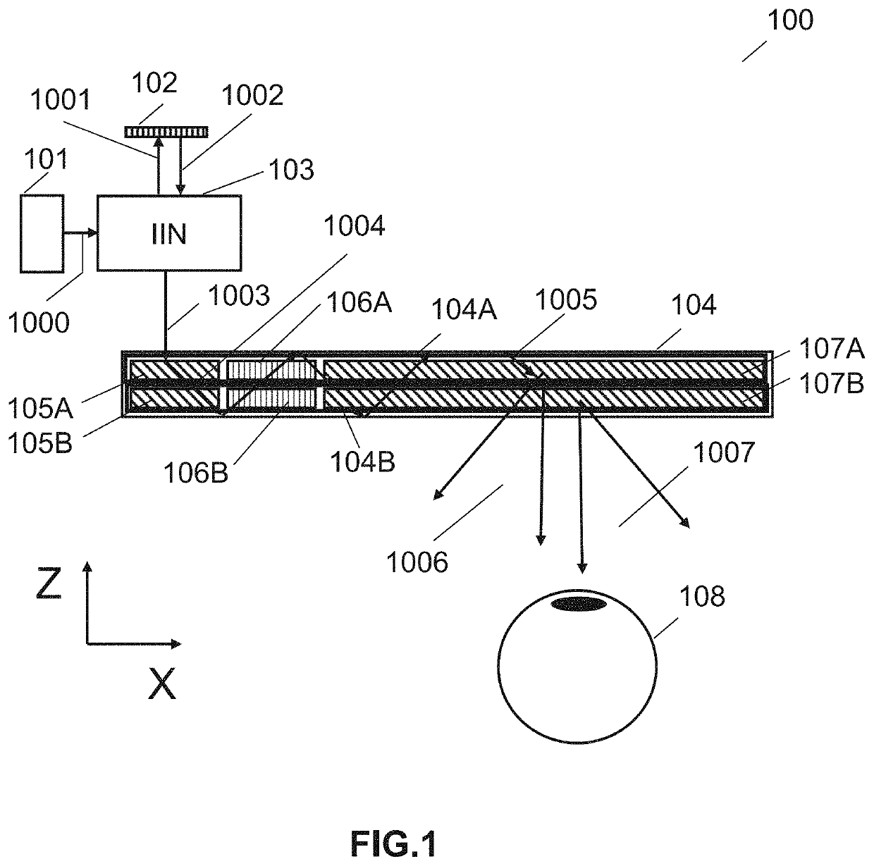
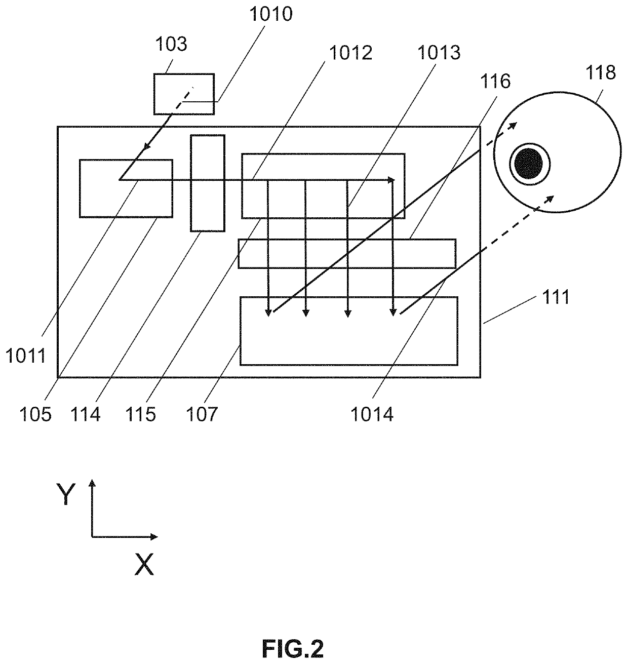
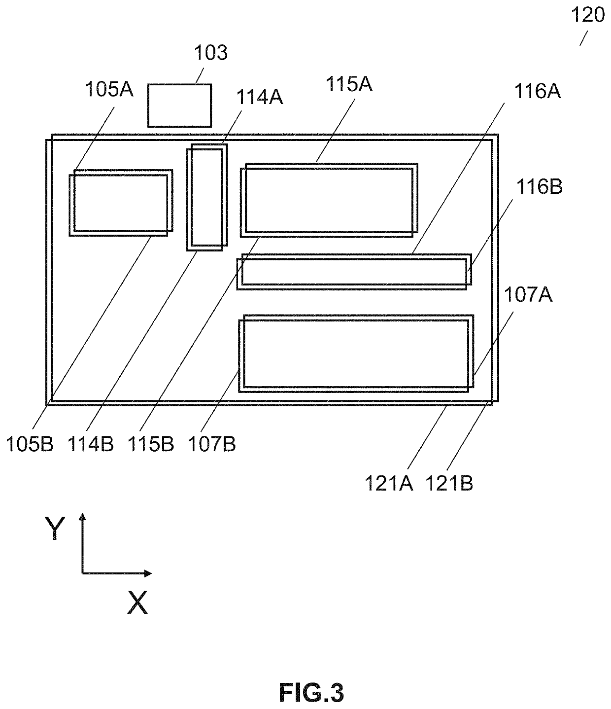
[0119]Referring generally to the Figures, systems and methods relating to near-eye display or head up display systems are provided according to various embodiments. Holographic waveguide technology can be utilized in waveguides for helmet mounted displays or head mounted displays (HMDs) and head up displays (HUDs) for many applications, including military applications and consumer applications (e.g., augmented reality glasses, etc.). Switchable Bragg gratings (SBGs) may be used in waveguides to eliminate extra layers and to reduce the thickness of current display systems, including HMDs, HUDs, and other near eye displays and to increase the field of view by tiling images presented sequentially on a microdisplay. A larger exit pupil may be created by using fold gratings in conjunction with conventional gratings to provide pupil expansion on a single waveguide in both the horizontal and vertical directions. Using the systems and methods disclosed herein, a single optical waveguide sub...


PUM

PropertyMeasurementUnit
thicknessaaaaaaaaaa
thicknessesaaaaaaaaaa
rake angleaaaaaaaaaa

Abstract

An optical display, including a first waveguide having a first set of surfaces, an input grating, a fold grating, and an output grating; an image input image node assembly; and a prismatic relay optics is provided. The prismatic relay optics may be configured to be optomechanically connected to the waveguide and the input image node assembly. The optical display is may also be configured to operate alone or as integrated with a headpiece to be used as a HUD. The HUD may have a first and a second configuration wherein the waveguide is decoupled or coupled.

Description

CROSS-REFERENCE TO RELATED APPLICATIONS[0001]The present application claims priority to U.S. Application No. 62 / 498,715, entitled “Waveguide Displays” to Waldern et al., filed Jan. 5, 2017, the disclosure of which is incorporated herein by reference in its entirety.FIELD OF THE INVENTION[0002]The present invention relates generally to displays including but not limited to near eye displays and more specifically holographic waveguide displays. Additionally, the present invention deals directly with the application of such displays in protective helmets.BACKGROUND[0003]Waveguide optics is currently being considered for a range of display and sensor applications for which the ability of waveguides to integrate multiple optical functions into a thin, transparent, lightweight substrate is of key importance. This new approach is stimulating new product developments including near-eye displays for Augmented Reality (AR) and Virtual Reality (VR), compact Heads Up Display (HUDs) for aviation...

Claims


Application Information

Patent Timeline
Patent Type & Authority Patents(United States)
IPC IPC(8): G09G5/00G06F3/043G02B27/00G06F3/042G02B27/01
CPCG02B27/0176G06F3/0421G06F3/0433G06F3/0436G02B27/0093G02B27/0172G02B2027/0174G02B2027/0169G02B2027/0125G02B2027/0187
Inventor WALDERN, JONATHAN DAVIDPOPOVICH, MILAN MOMCILOGRANT, ALASTAIR JOHN
Owner DIGILENS
Why Eureka
Try Eureka