

Pressure sensing catheter system
a catheter system and pressure technology, applied in the field of pressure sensing catheter systems, can solve problems such as withdrawal from social situations and reduced quality of li
- Summary
- Abstract
- Description
- Claims
- Application Information
AI Technical Summary
Benefits of technology
Problems solved by technology
Method used
Image

Examples
Embodiment Construction
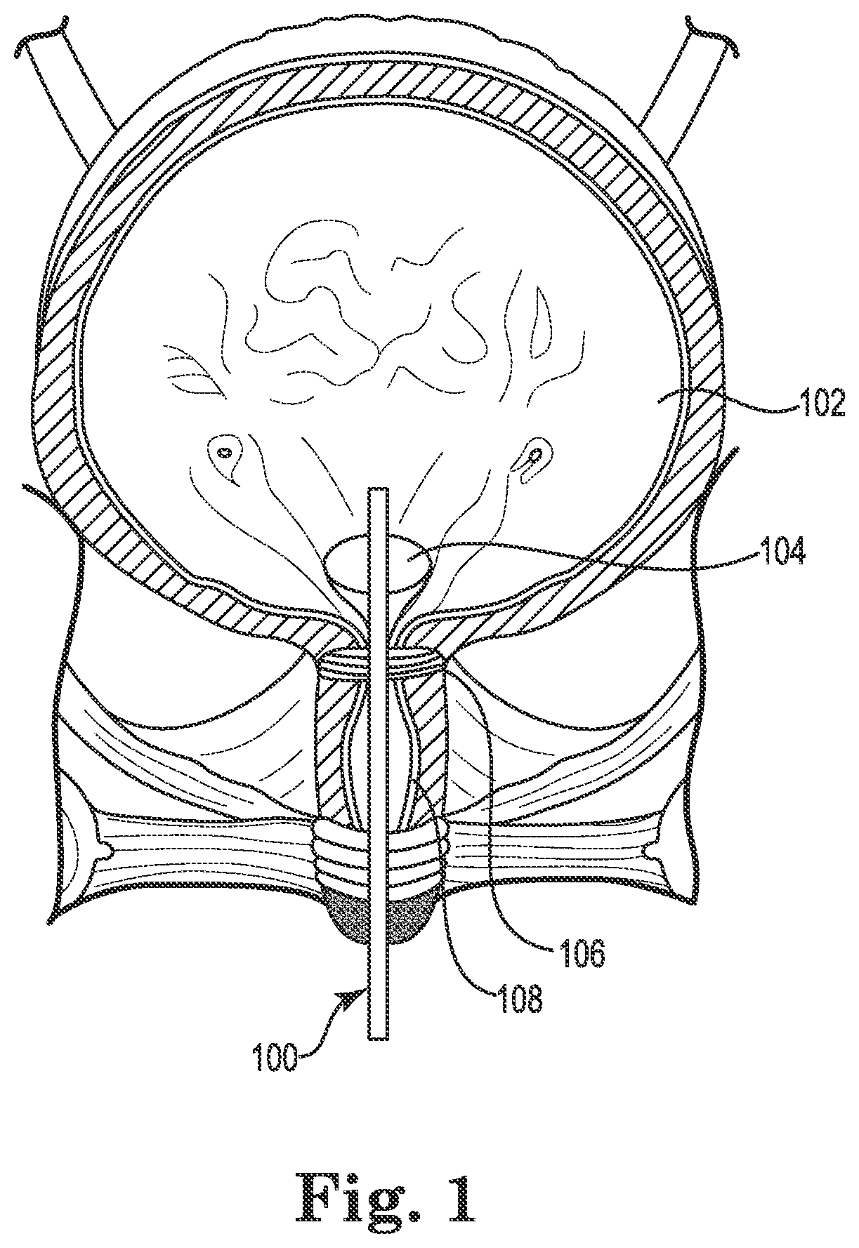
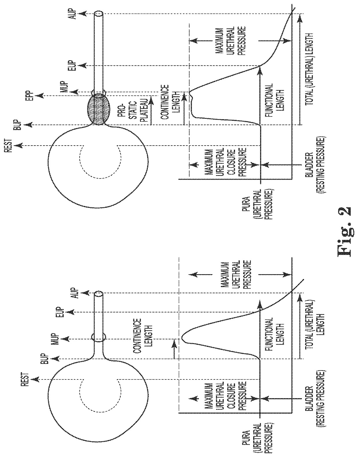
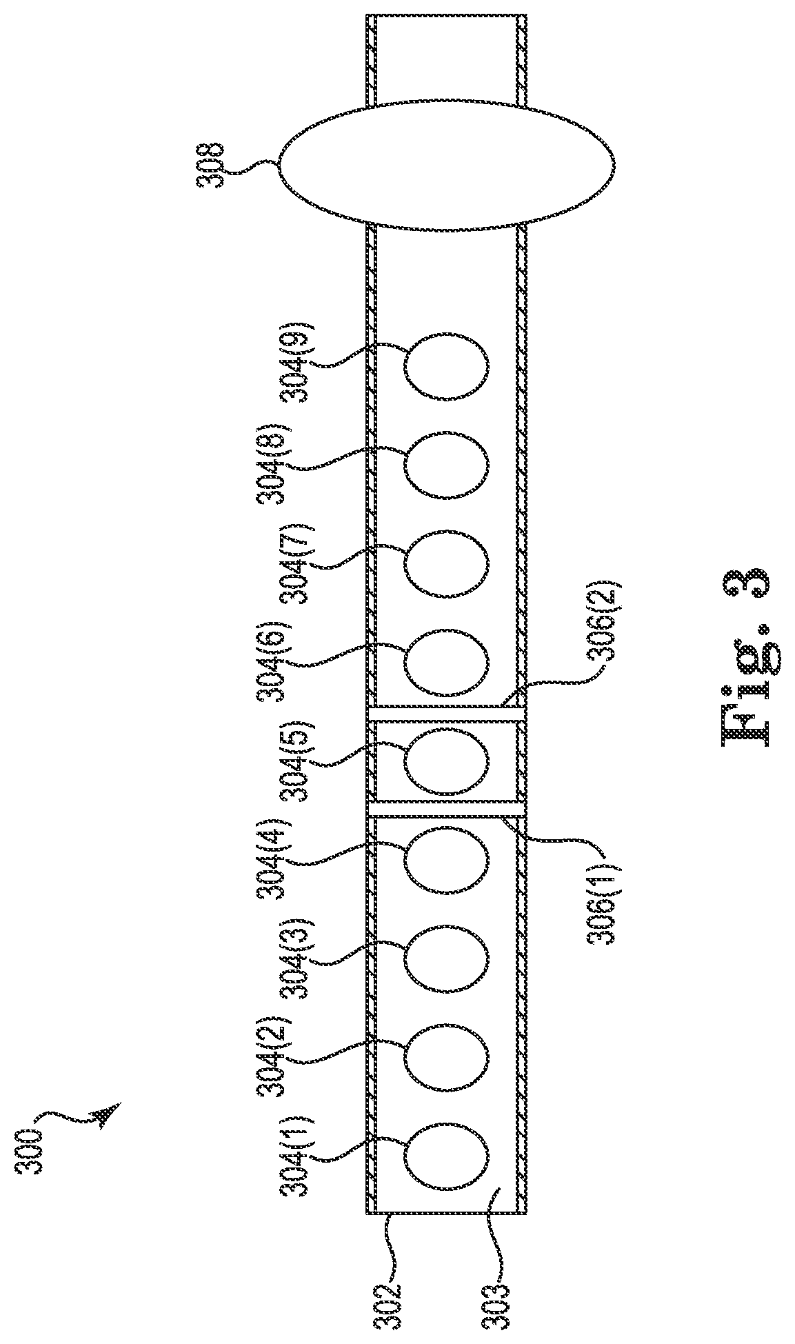
[0028]One embodiment is directed to a urethral catheter with a distributed micro-sensor strip (or sensor array) for improved urodynamics. The urethral catheter with the micro-sensor strip enables improved urodynamic diagnosis in subjects with urinary incontinence. The instrumented catheter can measure the dynamic pressure distribution profile along the urethra, which is not done with current urethral catheters. The pressure distribution measurements are combined with electromyography (EMG) measurements made on the same sensing strip to distinguish between neural and structural causes of urinary incontinence.
[0029]In one embodiment, the sensing strip is flexible in order to allow insertion into the male and female human urethra. Highly sensitive pressure sensors capable of measuring pressures as low as 0.1 psi are included on the strip. In one embodiment, the flexible sensing strip includes highly sensitive capacitive force sensors. The fabricated sensor strip according to one embodi...
PUM
 Abstract
Description
Claims
Application Information