
Slide rail assembly

a technology of slide rail and assembly, which is applied in the field of slide rail assembly, can solve the problems of not being able to use the above-mentioned operation mode, and the difficulty of developing a slide rail assembly for different maintenance purposes, and achieve the effect of facilitating maintenan

Active Publication Date: 2020-02-11
KING SLIDE WORKS CO LTD +1
View PDF21 Cites 5 Cited by
  • Summary
  • Abstract
  • Description
  • Claims
  • Application Information

AI Technical Summary

Benefits of technology

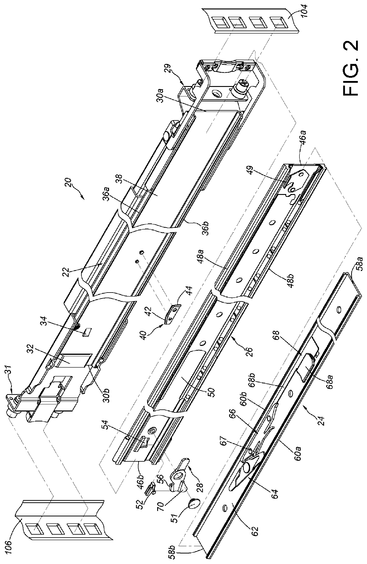
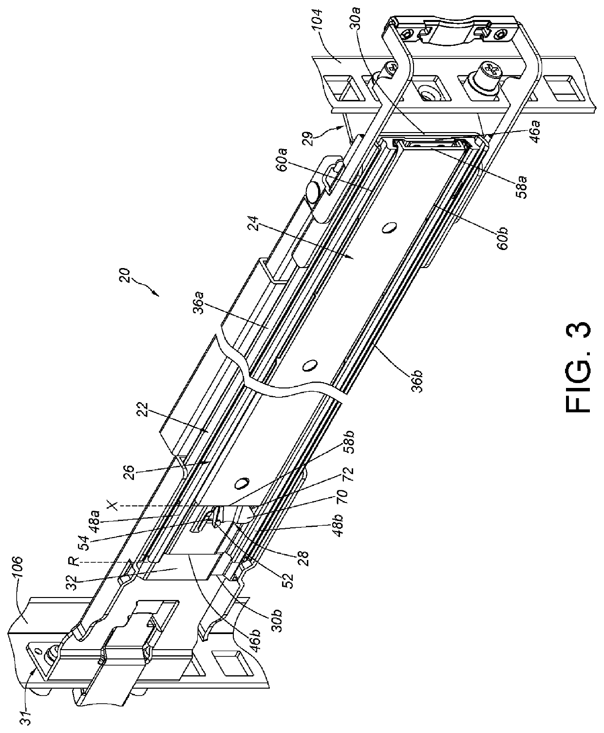
The present invention is about a slide rail assembly that makes maintenance easier. The assembly includes three rails: a first rail, a second rail, and a third rail. The first rail has a blocking structure to prevent the third rail from moving when it is in a retracted position. The second rail can move relative to the third rail to a specific position. The assembly also includes a working member that can switch the blocking structure to prevent the third rail from moving in an extended position. Additionally, there is an auxiliary member with a guiding portion and a blocking portion to prevent the third rail from moving in the retracted position.

Problems solved by technology

However, sometimes it is impossible to use the above-mentioned operation modes due to various requirements of maintenance of the slide rail assembly or the carried objects.
Accordingly, how to develop a slide rail assembly for different maintenance purpose has become an issue.

Method used


Image

  • Slide rail assembly
  • Slide rail assembly
  • Slide rail assembly

Examples


Embodiment Construction

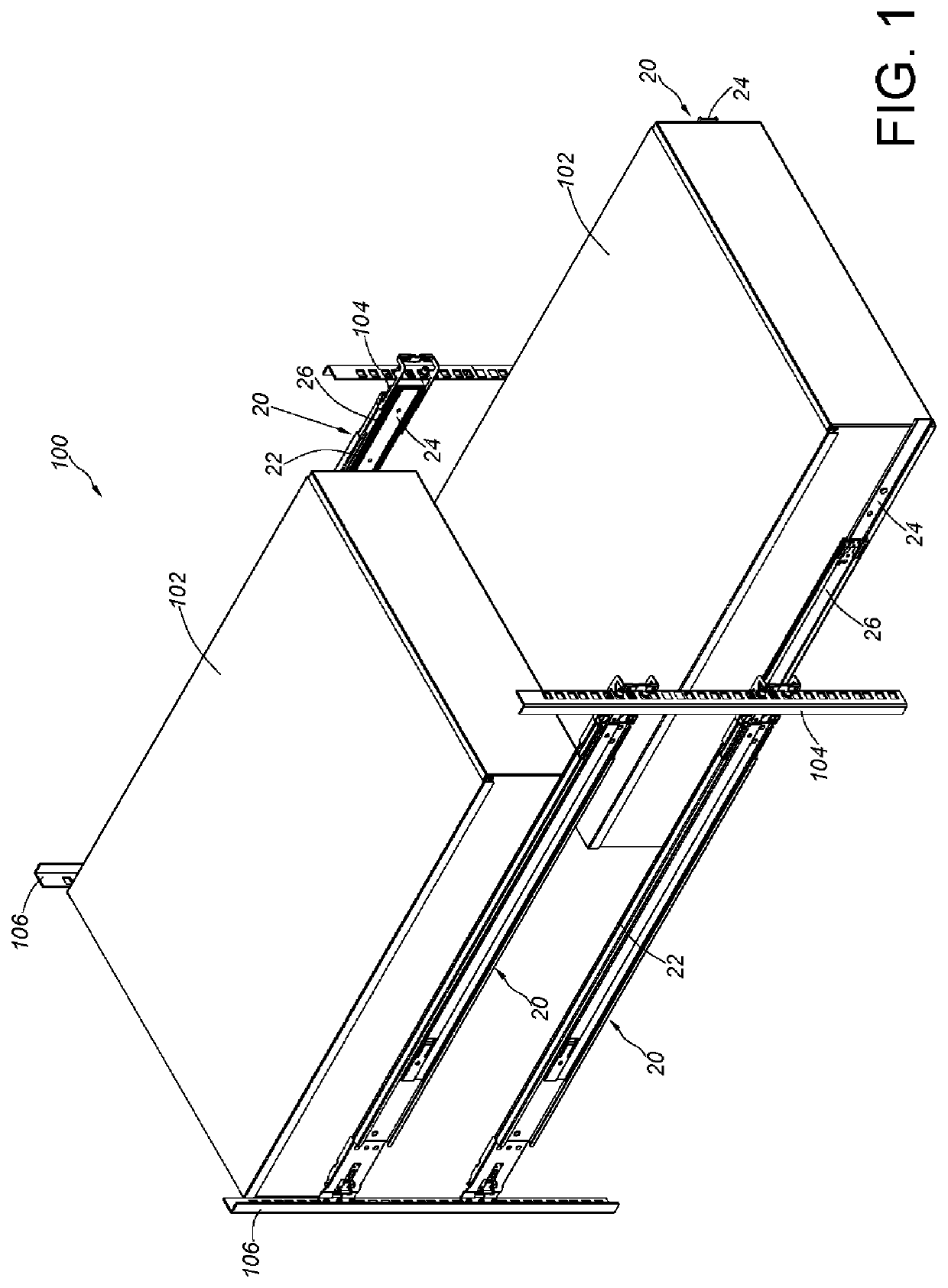
[0034]As shown in FIG. 1, in a rack system 100, a carried object 102 is configured as a drawer to be equipped with slide rail assemblies 20 on two opposite sides thereof, such that the carried object 102 is mounted to a rack, wherein the aforesaid rack includes a plurality of posts for each of the slide rail assemblies 20 to be mounted thereon. In practical application, the slide rail assembly 20 includes a first rail 22 and a second rail 24 movable relative to the first rail 22. Preferably, the slide rail assembly 20 further includes a third rail 26 mounted between the first rail 22 and the second rail 24, and the third rail 26 is configured to elongate displacement of the second rail 24 relative to the first rail 22.

[0035]Herein, two portions (e.g., a front portion and a rear portion) of the first rail 22 are mounted to a first post 104 and a second post 106 of the rack system 100. Further, the second rail 24 can be located at a closing position relative to the first rail 22, whic...


PUM


Abstract

A slide rail assembly includes a first rail, a second rail and a third rail. The third rail is mounted between the first rail and the second rail. The first rail includes a blocking structure. When the third rail is located at a retracted position with respect to the first rail, the blocking structure is used for preventing the third rail from being moved from the retracted position in a retracted direction. When the third rail is located at the retracted position, the second rail can be moved to a predetermined position in the retracted direction with a rear portion of the second rail being beyond a rear portion of the first rail by a distance.

Description

BACKGROUND OF THE INVENTION1. Field of the Invention[0001]The present invention relates to a slide rail assembly, and more particularly, to a slide rail assembly capable of facilitating maintenance for a carried object.2. Description of the Prior Art[0002]The drawings (e.g., FIG. 2) of U.S. Pat. No. 8,379,410 B2, invented by Kitten, discloses a plurality of carried objects (130, called chassis in the specification of the US patent). Both sides of each of the carried objects (130) are mounted to a rack (132) through support slides (134, 136), respectively. In use, each of the carried objects can only be moved out from the rack in a predetermined direction (e.g., the front side) to extend in front of the rack for facilitating repair or replacement parts or modules of the carried objects.[0003]However, sometimes it is impossible to use the above-mentioned operation modes due to various requirements of maintenance of the slide rail assembly or the carried objects. Accordingly, how to de...

Claims


Application Information

Patent Timeline
Patent Type & Authority Patents(United States)
IPC IPC(8): A47B88/49H05K7/14A47B88/403A47B88/477
CPCA47B88/477A47B88/49A47B88/403H05K7/1489A47B2210/0081A47B2210/0059
Inventor CHEN, KEN-CHINGYANG, SHUN-HOHO, CHUN-YIWANG, CHUN-CHIANG
Owner KING SLIDE WORKS CO LTD
Learn More