Display holder

a display and holder technology, applied in the field of display holders, can solve problems such as the drop of the display from the display holder, and achieve the effect of enhancing impact resistance and enhancing impact resistan

Active Publication Date: 2020-02-25
TOYOTA JIDOSHA KK
View PDF38 Cites 3 Cited by
  • Summary
  • Abstract
  • Description
  • Claims
  • Application Information

AI Technical Summary

Benefits of technology

The display mounting stand includes an arm that holds edges of the display, and a linear movement mechanism combined with the arm. Linear movement of the arm by the linear movement mechanism enables the position of the arm to follow the edges of the display, and this configuration realizes holding of displays with various dimensions. Meanwhile, an impact caused by a vehicle collision might decouple the arm from the linear movement mechanism, which results in dropping of the display from the display holder. Hence, the display holder is desired to have enhanced impact resistance. The present disclosure provides a display holder capable of enhancing impact resistance.
According to the above configuration, the movement of the arm relative to the rail and the movement of the rail relative to the holder are mutually interlocked with each other in the same direction. Accordingly, it is possible to rapidly hold the display between the holder and the arm in accordance with the dimension of the display.
Herein, when an impact is applied onto the display holder, such an impact acts on the rail such that the rail is bent toward the first support part or toward the second support part. The impact also acts on the arm such that the arm is bent toward the first linear moving part or the second linear moving part. With respect to the point, the first rack and the second rack are located on the side walls extending in one direction, that is, the portions having resistance against the above bending. Accordingly, with the above configuration, it is possible to suppress positional deviations of the first rack and the second rack relative to the respective gears. As a result, the meshing between the first rack and the first gear as well as the meshing between the second rack and the second gear are suppressed from being released, to thereby enhance impact resistance in the display holder.
The linear projection projecting in the thickness direction of the first support part has a structure to suppress the above-described bending, and the linear projection projecting in the thickness direction of the arm also has a structure to suppress the above-described bending. According to the above configuration, since the respective side walls on which the first rack and the second rack are located include the above linear projections, it is also possible to further suppress the meshing between the first rack and the first gear as well as the meshing between the second rack and the second gear from being out of engagement.
The above-described bending in the first support part 22 encourages a deformation such that the first support part 22 is pulled and stretched in one direction, thus displacing the first rack inward. The above-described bending of the arm encourages a deformation such that the arm is pulled and stretched in one direction, thus displacing the second rack inward. With respect to the point, according to the above configuration, the teeth of the first rack face inward of the first support part, and the teeth of the second rack face inward of the arm. Therefore, even if the above-described bending occurs, the deformation acts to maintain the meshing between the first rack and the first gear as well as maintain the meshing between the second rack and the second gear. Accordingly, it is possible to further suppress the meshing between the first rack and the first gear as well as the meshing between the second rack and the second gear from being out of engagement.
According to the above configuration, the movement of the arm relative to the rail is restricted by the arm restricting part to the linear movement along the one direction. The movement of the rail relative to the holder is restricted by the rail restricting part to the linear movement along the one direction. Accordingly, it is possible to effectively suppress the above meshing from being out of engagement, and also smoothly hold the display between the holder and the arm.

Problems solved by technology

Meanwhile, an impact caused by a vehicle collision might decouple the arm from the linear movement mechanism, which results in dropping of the display from the display holder.

Method used


Image

  • Display holder
  • Display holder
  • Display holder

Examples


Embodiment Construction

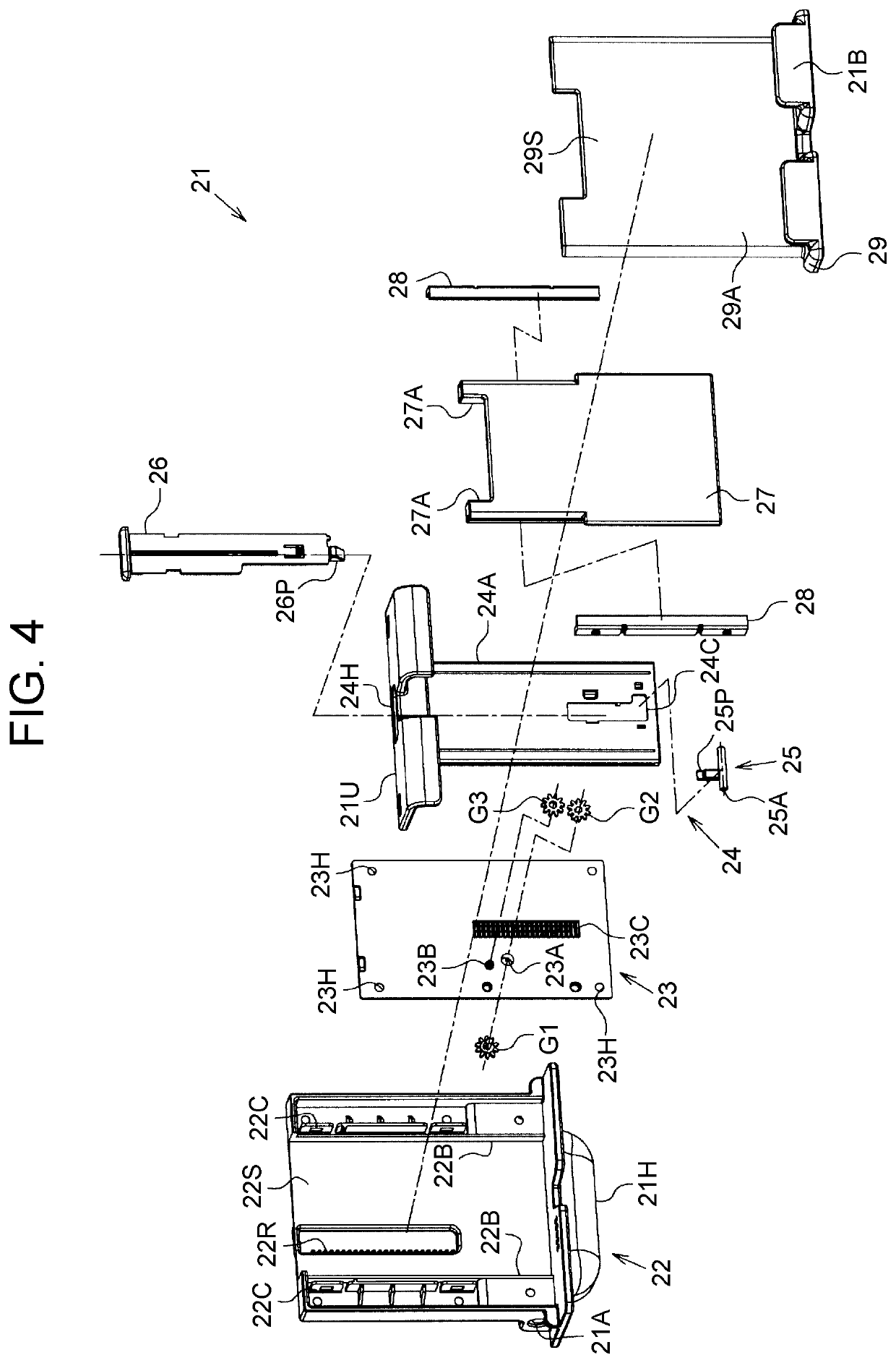
Hereinafter, one embodiment of a display holder will be described with reference to FIG. 1 to FIG. 7.

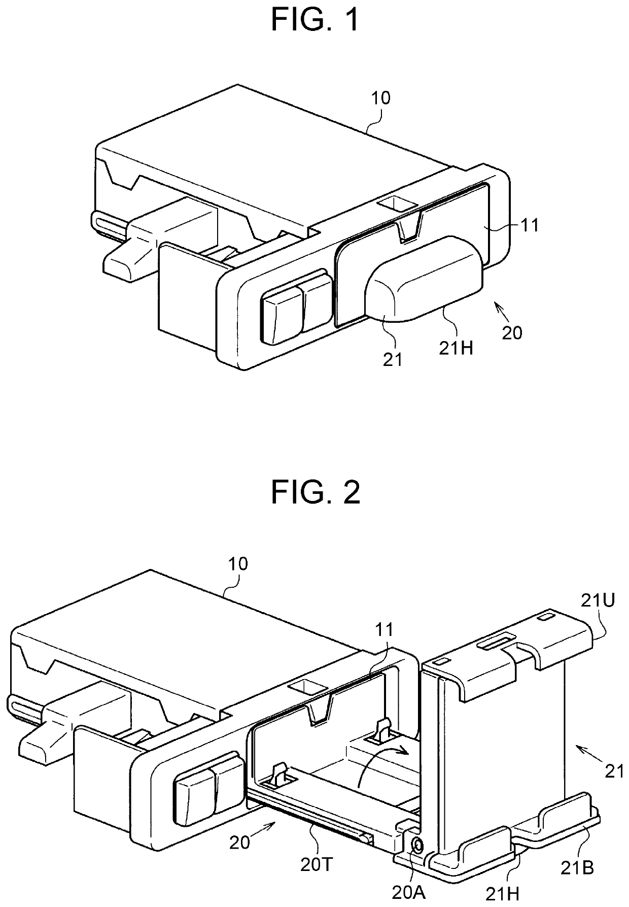
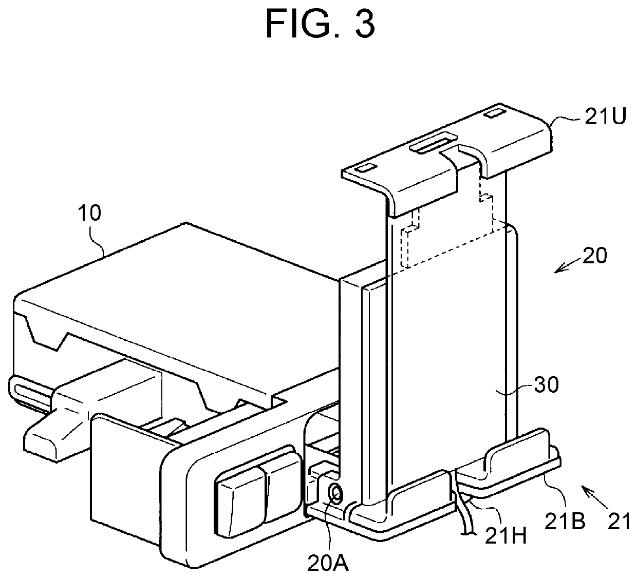
FIG. 1 shows a state in which a display mounting stand is accommodated in an accommodating part. FIG. 2 shows a state in which the display mounting stand is pulled out from the accommodating part, and is displaced from a laid-down posture to an upright posture. FIG. 3 shows a state in which a display is placed on the display mounting stand in the upright posture.

As shown in FIG. 1, the accommodating part 10 has a box-like shape, and is fixed to an instrument panel of the vehicle. The accommodating part 10 has an aperture 11 in a quadrangular shape facing a vehicle cabin. The accommodating part 10 accommodates a display holder 20 used for placing the display thereon.

The display holder 20 includes a display mounting stand 21. The display mounting stand 21 has a shape filling the aperture 11 of the accommodating part 10. The display mounting stand 21 includes a handle 21H. The handle 21...


PUM


Abstract

A display holder includes a display mounting stand. The display mounting stand includes a holder, a rail, an arm, a first gear, a second gear, and a third gear. The second gear and the third gear are located between the arm and a first linear moving part. The second gear is coaxially coupled to the first gear through a hole extending through the first linear moving part. The third gear meshes with the second gear and a second rack so as to interlock movement in one direction of the rail relative to the holder with movement in the one direction of the arm relative to the rail. A first rack is located on a side wall extending in the one direction of the first support part. The second rack is located on a side wall extending in the one direction of the arm.

Description

CROSS-REFERENCE TO RELATED APPLICATIONSThis application claims priority to Japanese Patent Application No. 2018-016778 filed on Feb. 1, 2018, which is incorporated herein by reference in its entirety including the specification, drawings and abstract.BACKGROUND1. Technical FieldThe present disclosure relates to a display holder accommodated in an instrument panel of a vehicle.2. Description of Related ArtThe above display holder includes a display mounting stand, and a display, such as a smartphone or a tablet computer, is placed on the display mounting stand. The display mounting stand is configured to be accommodated in an instrument panel or pulled out from the instrument panel in a laid-down state. The display mounting stand is pulled up from a pulled-out state, and then retains the display in an upright state (see Published Japanese Translation of PCT Application No. 2016-500353, for example).SUMMARYThe display mounting stand includes an arm that holds edges of the display, and...

Claims


Application Information

Patent Timeline
Patent Type & Authority Patents(United States)
IPC IPC(8): B60R11/02B60R7/06B60R11/00
CPCB60R11/0235B60R11/02B60R11/0241B60R11/0252B60R2011/0085B60R2011/0082B60R2011/0075B60R2011/0005B60R2011/008B60R2011/0084B60R2011/027B60R2011/0003B60R11/0229
Inventor YAMADA, TAKAKOFUJIWARA, YASUHISAHASEGAWA, KUNIAKIMAEDA, YOSHINARIKAWAMURA, YUKINORI
Owner TOYOTA JIDOSHA KK
Why Eureka
Try Eureka