Locking mechanism for an electrical assembly, and assembly comprising a locking mechanism

a technology of locking mechanism and electrical assembly, which is applied in the direction of electrical apparatus, basic electric elements, connections, etc., can solve the problems of reduced elastic property and achieve the effect of convenient access and simplified operation of the locking mechanism

Active Publication Date: 2020-02-25
HORA WERK
View PDF10 Cites 0 Cited by
  • Summary
  • Abstract
  • Description
  • Claims
  • Application Information

AI Technical Summary

Benefits of technology

The advantage of the detent mechanism proposed herein is that a detent hook bracket that is intended for deflecting the detent hook is guided by limiting means, and that this guiding of the detent hook bracket limits movability of the detent hook bracket when the detent hook is deflected, and thus also limits movability of the detent hook as a whole.
As a result of limiting the movability of the detent hook, it is not possible for the detent hook to be damaged or even torn off, even under excessive application of force. Also as a result of limiting the movability of the detent hook, the detent hook web is not overstressed (overstretched) when the detent hook is deflected, and thus maintains the elasticity provided within the scope of the particular material properties, even after numerous locking operations and subsequent releases of the detent connection. The detent mechanism is economical, since it may be manufactured from the material of the housing for the particular assembly and may be joined to the housing in one piece. In such an embodiment, the detent mechanism is an integral part of the housing of the particular assembly, and does not require an additional mounting step during manufacture of the assembly in question.
In one advantageous embodiment of the detent mechanism, the detent hook web is inclined, at least in sections. The inclination is with respect to a normal to the particular side face from which the detent hook web emerges, i.e., typically with respect to a normal to the bottom side of the assembly. The direction of inclination points away from the area between the movable detent hook and at least one oppositely situated rigid detent hook. The support rail is situated in this area when an assembly is snapped on. Accordingly, this direction of inclination is referred to below for short as an inclination facing away from the support rail. Better load capacity of the detent connection results due to the detent hook web being inclined, at least in sections, in this way. The improved load capacity is provided due to the fact that, for a tensile load that acts on an assembly that is snapped onto a support rail, the inclined detent hook web is increasingly raised up due to the tensile load. This raising results in improved and durable locking of the assembly to the support rail.
As a result, the fixing of the particular assembly in the snapped-on state on the support is much more durable, in particular more durable against vibration loads, even extreme vibration loads, and more resistant to improper attempts to release the locking of the assembly to the support rail.
In a further or alternative embodiment of the detent mechanism, at least one pair of guide ribs that are placed above and below a plane defined by the detent hook bracket function as limiting means. The guide ribs ensure that the detent hook bracket is guided in a plane defined by the position of the guide ribs when the detent hook is deflected. As a result of the guide ribs themselves being mounted above and below the plane defined by the detent hook bracket, the detent hook bracket always remains in the same plane or at least essentially in the same plane when the detent hook is deflected. Thus, when the detent hook is deflected, the detent hook bracket cannot be pivoted out of the plane that is provided for a translational movement of the detent hook bracket, and, for example, cannot be raised up and thus bent or broken off. This ensures that the detent hook bracket is not damaged, even when the detent connection is released multiple times, and thus likewise ensures that the detent mechanism as a whole remains usable over a long period of time. In addition, the fixing of the detent hook bracket in the plane defined by the guide ribs simplifies operation of the detent mechanism when the detent connection is released, since, due to the guide ribs, the detent hook bracket is always situated slightly above a mounting plate or the like, for example, on which the particular support rail is mounted and to which the assembly is locked. At that location the detent hook bracket may be easily accessed with a tool, for example a screwdriver, for example by inserting the blade of the screwdriver into a recess provided for this purpose on the free end of the detent hook bracket. Without the fixing of the detent hook bracket in the plane defined by the guide ribs, after several actuation operations the detent hook bracket may be raised upwardly to some extent (away from a possible mounting plate) or pressed downwardly to rest on the mounting plate in the downwardly pressed state. At that location the blade of the screwdriver can be inserted into the recess at the end of the detent hook bracket only until contact is made with the mounting plate. This increases the risk of the blade of the screwdriver slipping off when the detent hook bracket moves. In addition, the mounting plate may be scratched by contact with the blade of the screwdriver.
In yet another embodiment of the detent mechanism, the detent hook bracket has a reduced-material section along its longitudinal extension. In the material-reduced section, the detent hook bracket is thinner than in the area laterally next to the material-reduced section. The material-reduced section ensures elastic movability of the detent hook bracket in this area, transversely with respect to the longitudinal extension thereof. When the detent hook is deflected, not only does elastic deformation of the detent hook take place in the area of its detent hook web, but also elastic deformation of the detent hook bracket takes place in the area of its material-reduced section. The detent hook bracket may thus optimally follow the pivoting motion of the detent hook web that is triggered when the detent hook bracket is actuated, in that the detent hook bracket becomes increasingly bent in the material-reduced section the more the detent hook web is pivoted. The portion adjoining the material-reduced section up to the free end of the detent hook bracket remains in its intended horizontal or essentially horizontal orientation.

Problems solved by technology

However, if excessive force is applied, such a detent hook web may even break in whole or in part, so that when a detent hook web is torn off, locking of the particular assembly to a support rail is no longer possible, and with a partially broken or overloaded detent hook web the elastic property is often reduced so greatly that when the particular assembly is pivoted onto the support rail, the detent hook web no longer springs back into a configuration in which the detent lug situated at the end of the detent hook securely engages beneath the support rail.

Method used


Image

  • Locking mechanism for an electrical assembly, and assembly comprising a locking mechanism
  • Locking mechanism for an electrical assembly, and assembly comprising a locking mechanism
  • Locking mechanism for an electrical assembly, and assembly comprising a locking mechanism

Examples


Embodiment Construction

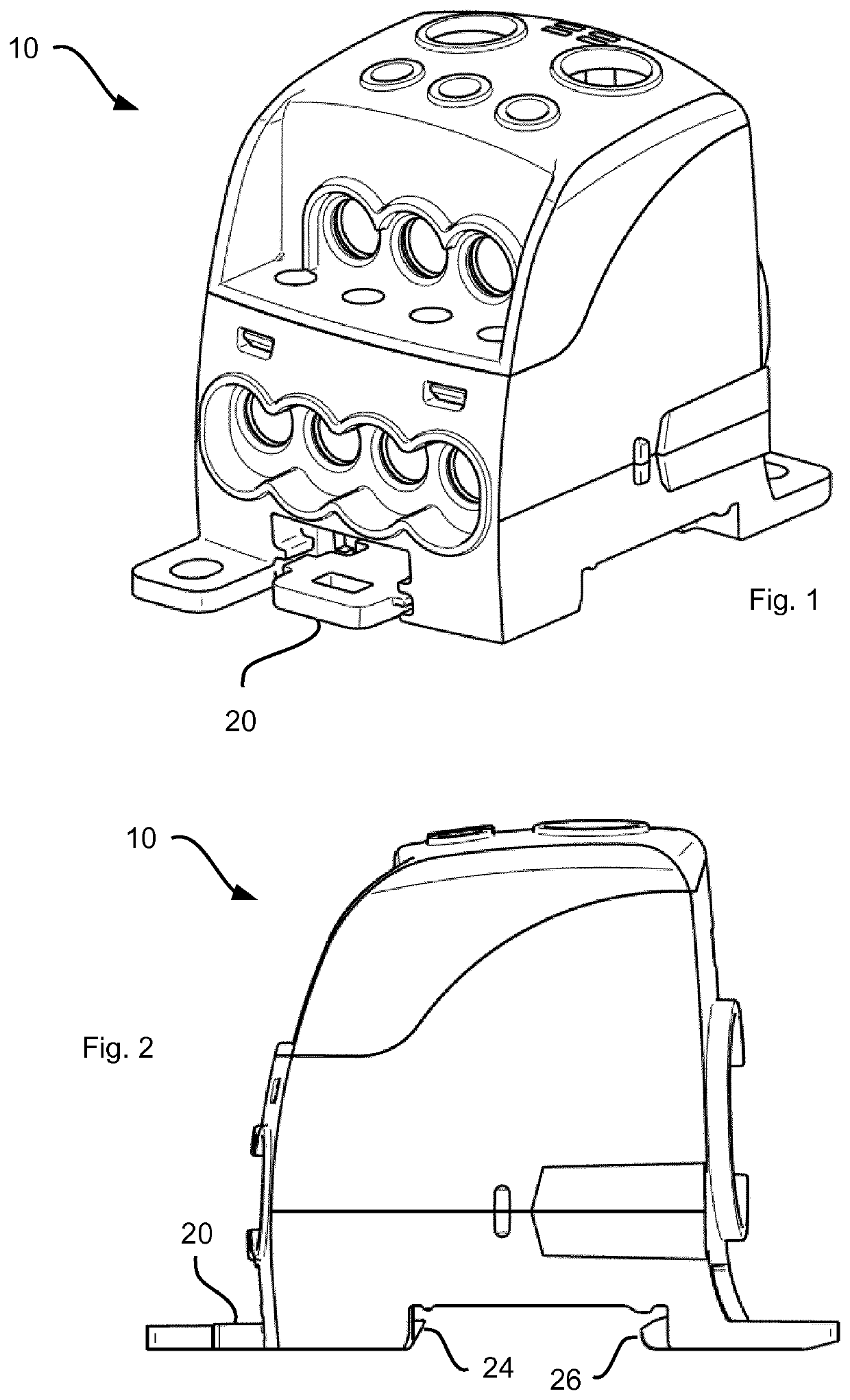
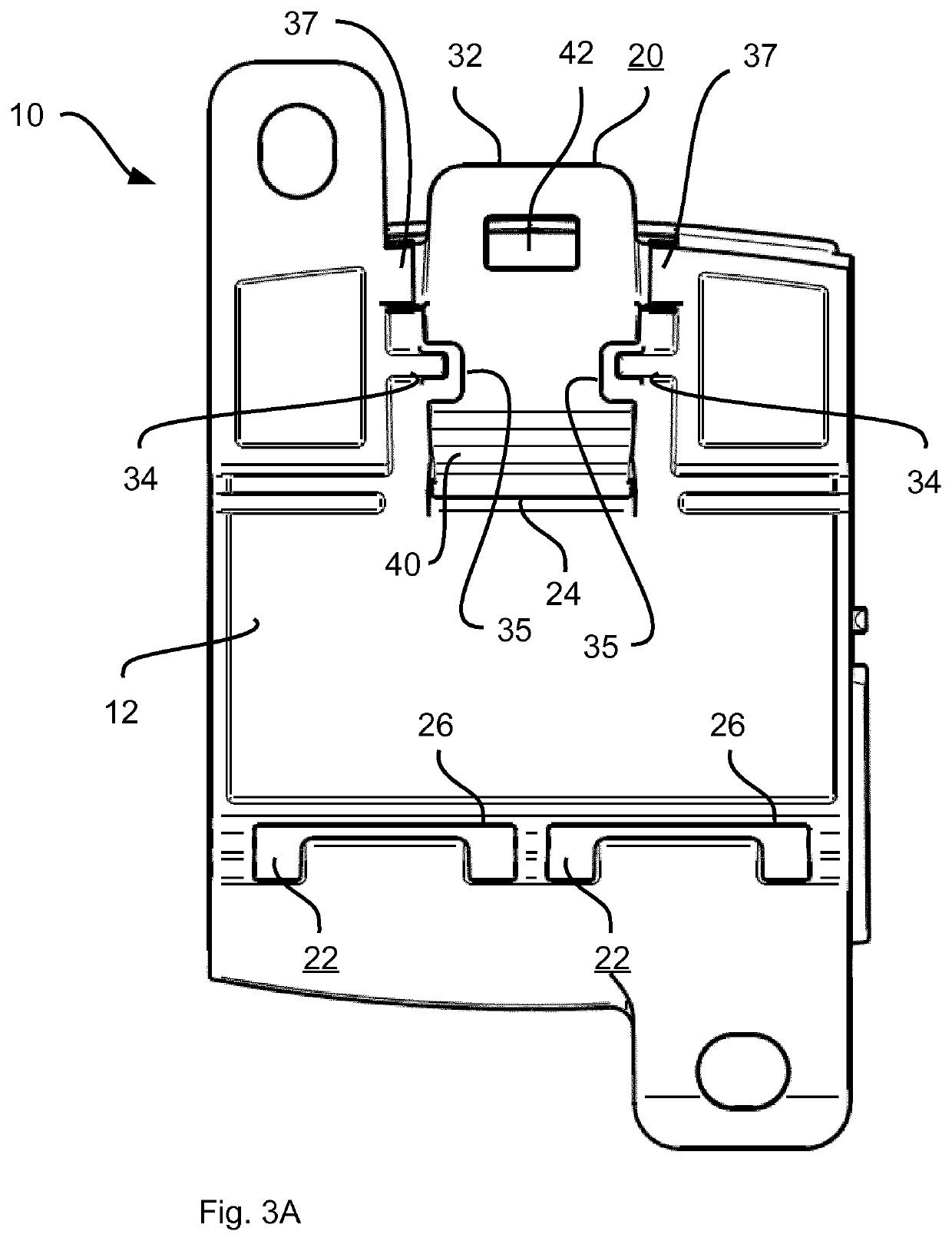
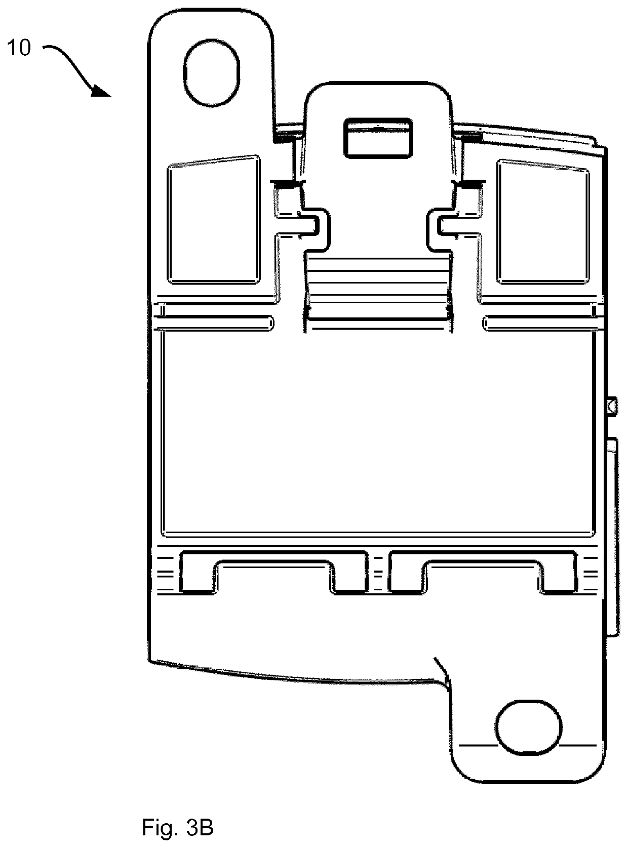
The illustrations in FIG. 1 and FIG. 2 show, as an example of an electrical assembly 10 of the type under discussion here, a distribution block / a distribution terminal similar to the distribution terminal described in DE 20 2010 005 216 U1. The illustrations in FIGS. 3A, 4A, and 5A correspond to the illustrations in FIGS. 3B, 4B, and 5B, with the reference lines and reference numerals omitted in the illustrations in FIGS. 3B, 4B, and 5B for better clarity.

The illustrations in FIGS. 3A, 3B show a bottom side 12 of the assembly 10 according to FIG. 1 and FIG. 2. The assembly 10 is provided for snapping onto a support rail 14 (FIG. 6). For this purpose, the bottom side 12 of the assembly 10 has a corresponding design, and has a detent mechanism in the form of at least one movable detent hook 20 and at least one rigid detent hook 22. The movable detent hook 20 and the, or each, rigid detent hook 22 are oppositely placed, facing one another, on the bottom side 12 of the assembly 10. A di...


PUM


Abstract

A locking mechanism (20, 22) for an electrical assembly (10). The locking mechanism (20, 22) has a detent hook (20) that is hinged to the electrical assembly (10) by a flexible detent hook web (30), and a detent hook bracket (32) that is used for deflecting the detent hook (20). Limiting structures (34, 35, 36, 37, 38) restrict mobility of the buckle bracket (32) when the detent hook (20) is deflected. The locking mechanism (20, 22) may be applied in an electrical assembly, such as terminals, distribution terminals or other electrical connection devices, fuse holders, etc., as well as switching devices such as protectors, motor protection switches and the like.

Description

BACKGROUND OF THE INVENTIONThe invention relates primarily to a detent mechanism for an electrical assembly or an electrical device, collectively referred to below as an electrical assembly. Electrical assemblies are understood to mean terminals, distribution terminals, or other electrical connection devices, fuse holders, etc., as well as switching devices such as protectors, motor protection switches, and the like. Moreover, the invention relates to such an electrical assembly having a detent mechanism.With these types of assemblies, mounting in a terminal box, distribution box, or a so-called switch cabinet is common. The mounting takes place on or at a support rail or mounting rail provided for this purpose. Such rails have a profile that is provided for detachably mounting (snapping on, snapping off) an assembly or a plurality of assemblies. One example of such a profile is a so-called top-hat profile of a corresponding support rail, referred to as a top-hat profile rail, or to...

Claims


Application Information

Patent Timeline
Patent Type & Authority Patents(United States)
IPC IPC(8): H02B1/052H01R9/26
CPCH02B1/0523H01R9/2608
Inventor NIESTRAT, DIRKHOLTMANN, RALF
Owner HORA WERK
Why Eureka
Try Eureka