Height-adjustable spring arrangement for a vehicle

a technology for height adjustment and spring arrangement, which is applied in the direction of shock absorbers, cycles, transportation and packaging, etc., can solve the problems of negative spring travel of the spring, the effect of spring prestress is so small, and the minimum value of spring prestress is undersho

Active Publication Date: 2022-05-10
BAYERISCHE MOTOREN WERKE AG
View PDF45 Cites 0 Cited by
  • Summary
  • Abstract
  • Description
  • Claims
  • Application Information

AI Technical Summary

Benefits of technology

[0002]The prior art has already disclosed a multiplicity of different spring arrangements for motor vehicles, which spring arrangements are height-adjustable and, as a result, make a driving position change or driving position setting of the vehicle possible.
[0011]The first limiting cylinder is configured, in particular, as a linear drive, and the second limiting cylinder is configured as an equalizing vessel which at the same time limits the movability of the bearing spring along the negative spring travel. In order to raise the vehicle, a fluid, such as oil or air, for example, can be pumped by way of a pump out of the second limiting cylinder into the first limiting cylinder, as a result of which the first limiting piston is displaced with respect to the first limiting cylinder pot, and the guide piston rod is displaced, and the height of the spring arrangement is increased. In order to lower the spring arrangement, a force, for example the weight of the vehicle, acts on the first limiting cylinder, as a result of which the fluid is pumped out of the first limiting cylinder into the second limiting cylinder. Here, the second limiting cylinder limits the negative spring travel in a manner which is dependent on the fluid which is pumped out of the first limiting cylinder.
[0017]One advantageous development of the spring arrangement additionally provides that the first limiting cylinder has a first fluid chamber which is formed by way of the first limiting cylinder pot and the first limiting piston, and the second limiting cylinder has a second fluid chamber which is formed by way of the second limiting cylinder pot and the second limiting piston. The first fluid chamber and the second fluid chamber are connected in terms of flow by way of a fluid channel, with the result that fluid can flow through the fluid channel between the first and the second fluid chamber.

Problems solved by technology

In the case of the height-adjustable spring arrangements which are known in the prior art, however, it can occur that the negative spring travel of the spring becomes so great as a result of lowering of the driving position of the vehicle and the effective spring prestress becomes so small that a minimum value of the spring prestress is undershot.
As a result of the reduction of the spring prestress and the undershooting of the minimum value, the bearing spring can be damaged in the case of rebound, that is to say in the case of a spring movement along the negative spring travel, or can cause a negative driving behavior of the motor vehicle.
For example, as a result of the excessively small spring prestress, the bearing spring can slip from the spring mounting or spring collar during rebound, as a result of which an asymmetrical introduction of spring force into the motor vehicle can occur in the case of a subsequent load.
Furthermore, acoustically perceivable noise which can unsettle the driver of the motor vehicle occurs.
As a result of a leak at the first fluid chamber, the second fluid chamber or at the fluid channel, it can occur that sufficient fluid is no longer present in the fluid system which consists of the first fluid chamber, the second fluid chamber and the fluid channel.

Method used


Image

  • Height-adjustable spring arrangement for a vehicle
  • Height-adjustable spring arrangement for a vehicle

Examples


Embodiment Construction

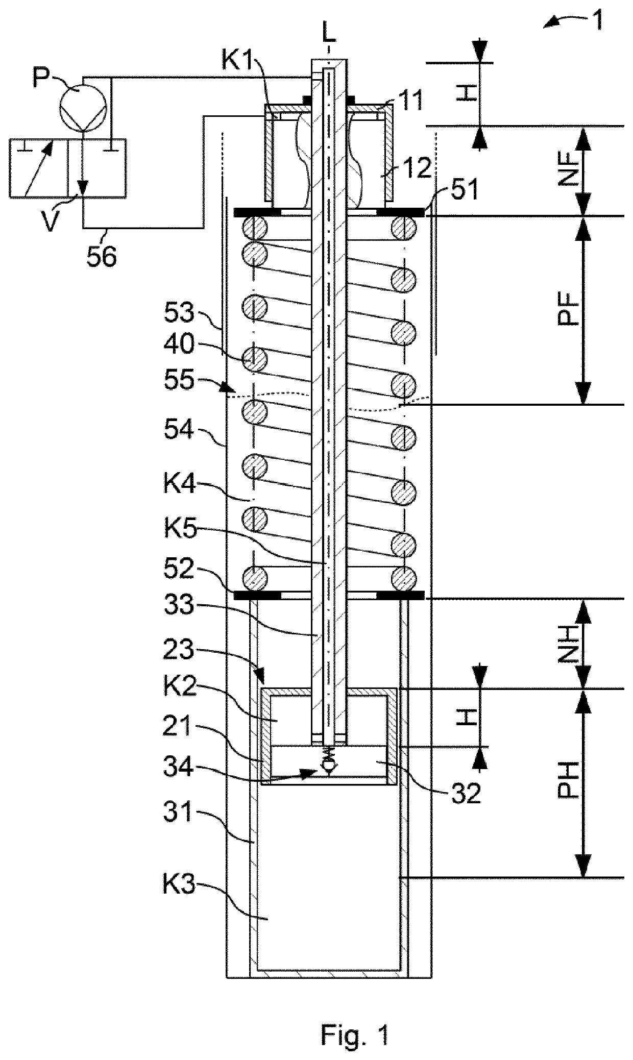
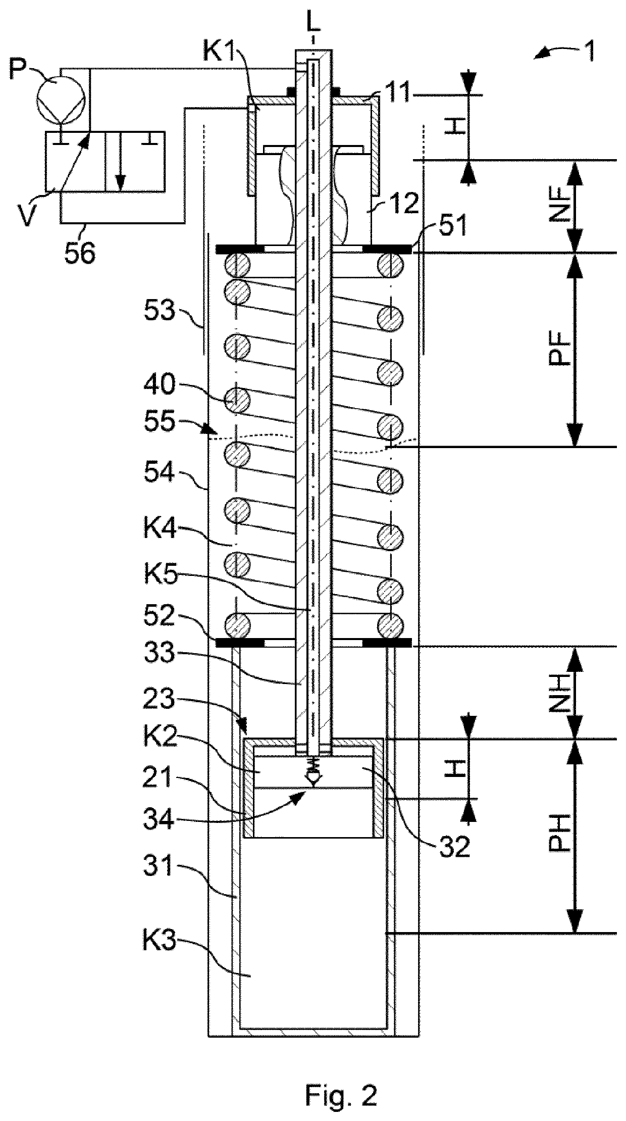
[0034]The figures are diagrammatic by way of example. Identical designations in the figures indicate identical functional and / or structural features.

[0035]FIGS. 1 and 2 each show an embodiment of the spring arrangement 1 according to the invention, wherein all components are illustrated in half-section.

[0036]The spring arrangement 1 is arranged in a stationary tube 54 and in a sliding tube 53 which surrounds the stationary tube 54. Furthermore, the spring arrangement 1 is formed substantially by way of a first limiting cylinder, a second limiting cylinder, a guide cylinder and a bearing spring 40. The guide cylinder has a guide cylinder pot 31 which is arranged in the stationary tube 54 and is open on one side. A guide piston is arranged in the guide cylinder pot 31, on which guide piston the guide piston rod 33 is fixed which extends out of the guide cylinder pot 31 on the open side of the guide cylinder pot 31, and extends through the bearing spring 40.

[0037]The first limiting cyl...


PUM


Abstract

A height-adjustable spring arrangement for a vehicle includes a bearing spring, a first limiting cylinder with a first limiting cylinder pot and a first limiting piston, a second limiting cylinder with a second limiting cylinder pot and a second limiting piston, and a guide cylinder with a guide cylinder pot, a displaceable guide piston in the guide cylinder pot and a guide piston rod fixed on the guide piston and extending out of the guide cylinder pot along a longitudinal axis of a bearing spring and through the bearing spring. The guide piston rod is displaceable by the first and second limiting cylinders such that a spring preload acting on the bearing spring and a negative spring path of the bearing spring remain constant as a result of a height adjustment.

Description

BACKGROUND AND SUMMARY OF THE INVENTION[0001]The invention relates to a height-adjustable spring arrangement for a motor vehicle.[0002]The prior art has already disclosed a multiplicity of different spring arrangements for motor vehicles, which spring arrangements are height-adjustable and, as a result, make a driving position change or driving position setting of the vehicle possible.[0003]In particular, in the case of single track motor vehicles, such as motorcycles, for example, the driving position or ride height of the vehicle has a great influence on the driving behavior and the steering geometry. Both the stability and the handling of the vehicle are greatly dependent on the driving position, the motor vehicles usually being designed for a predefined setpoint driving position.[0004]Most of the spring arrangement in motor vehicles have a bearing spring with a segment-specific stroke behavior, which bearing spring is clamped in between spring collars or spring mountings. The be...

Claims


Application Information

Patent Timeline
Patent Type & Authority Patents(United States)
IPC IPC(8): B60G17/027B60G3/01
CPCB60G17/0272B60G3/01B60G2202/416B60G2204/4232B60G2206/42B60G2500/30B60G2300/12B60G2500/322F16F1/121B60G2202/413B60G2800/914B60G2202/44B60G2204/16F16F9/103F16F9/56
Inventor DIETRICH, MAXIMILIANRIEDIGER, MARTINSCHATZBERGER, UWE
Owner BAYERISCHE MOTOREN WERKE AG
Why Eureka
Try Eureka