Resonant converter with magnetic-flux balance control circuit

Active Publication Date: 2020-03-03
NAT TAIWAN UNIV
View PDF6 Cites 11 Cited by
  • Summary
  • Abstract
  • Description
  • Claims
  • Application Information

AI Technical Summary

Benefits of technology

[0016]In order to solve the abovementioned problem, the present invention discloses a LLC resonant converter with magnetic-flux control circuit, which can be used in the LLC resonant converter for controlling and estimating the transformer m

Problems solved by technology

Due to the non-ideality property of circuit, the magnetic-flux unbalance will be generated to cause the magnetic-flux saturation problem of transformer.
However, the characteristics of each switch and the performance of driven circuit may not be all the same in the hardware performance, so that the positive half cycle and the negative half cycle of generated high-frequency square wave voltage will not be totally symmetrical, and then cause the magnetic-flux unbalance phenomenon.
The leakage inductor of two windings, the winding resistor, the resistor on the trace of PCB, and the characteristics of rectifier elements are inconsistent, so that the unbalanced magnetizing current is occurred at the primary-side, resulting in the generation of magnetic flux shift phenomenon.
All of them can generate the magnetic-flux unbalance phenomenon.
Thus, all will also face the magnetic-flux unbalance problem to cause the transformer magnetic-flux saturation.
However, in the conventional LLC resonant converter, the abovementioned serial capacitor is unable to

Method used


Image

  • Resonant converter with magnetic-flux balance control circuit
  • Resonant converter with magnetic-flux balance control circuit
  • Resonant converter with magnetic-flux balance control circuit

Examples


Example

[0045]Please refer to FIG. 3, FIG. 3 illustrates a schematic diagram of the LLC resonant converter with magnetic-flux control circuit for an embodiment of the present invention.

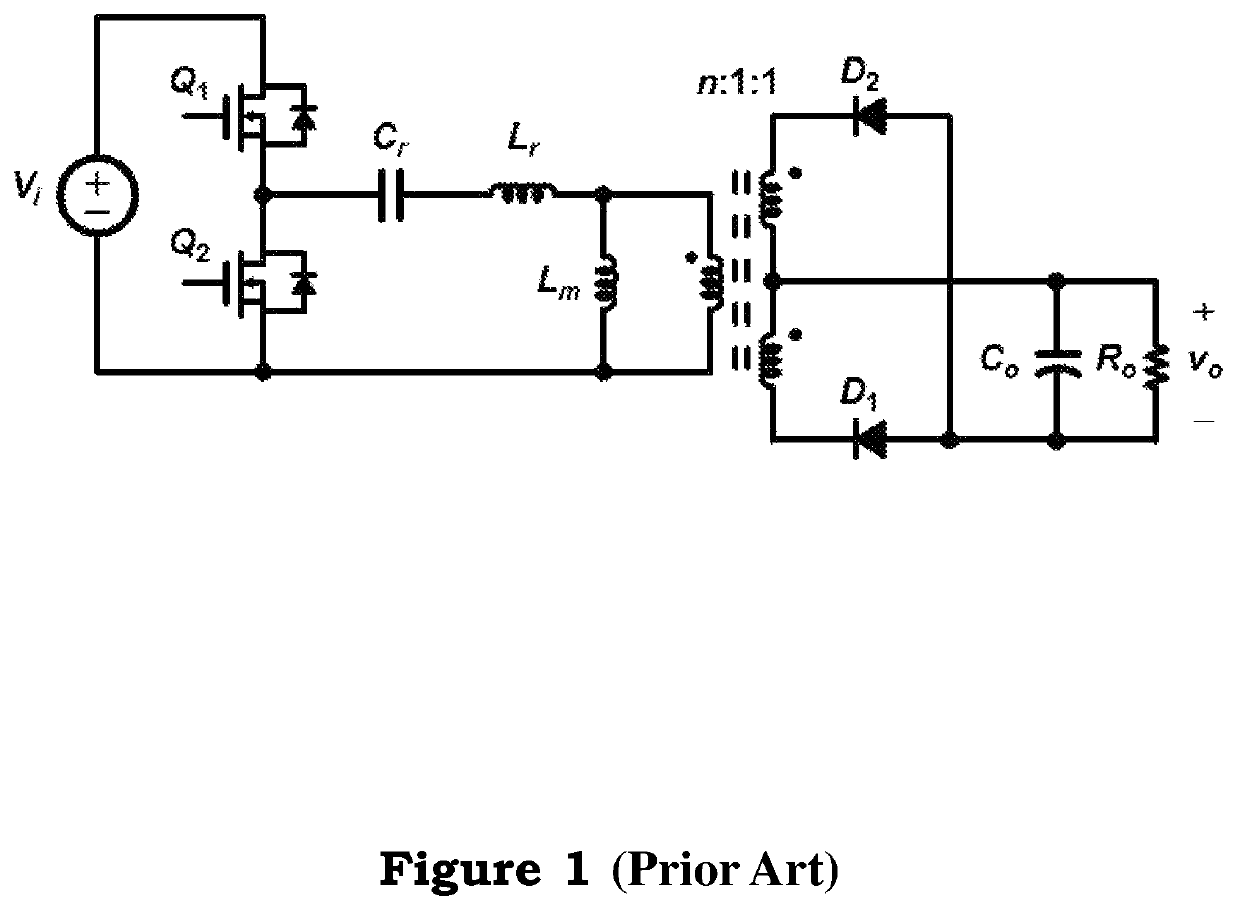
[0046]Please refer to FIG. 3 again, which illustrates the LLC resonant converter with magnetic-flux control circuit 300, including a LLC resonant converter 302, and a control unit 320. The LLC resonant converter 302 includes a primary-side circuit 3022 and a secondary-side circuit 3024, wherein the primary-side circuit 3022 includes a primary-side winding Np, a resonant capacitor Cr, a resonant inductor Lr, a magnetizing inductor Lm, a first switch Q1, a second switch Q2, and a DC power source Vi. The secondary-side circuit 3024 includes a secondary-side winding Ns, a first diode D1, a second diode D2, an output capacitor Co, and an output resistor Ro. The secondary-side winding Ns includes a first secondary-side winding Ns1 and a second secondary-side winding Ns2. The control unit 320 includes a voltage cont...


PUM


Abstract

The present invention provides a LLC resonant converter with magnetic-flux balance control circuit. The LLC resonant converter comprises a primary-side circuit and a secondary-side circuit, wherein the control loop of secondary-side circuit comprises a voltage control unit, a digital pulse-width-modulation generation unit, and the control loop of primary-side circuit comprises a DC detection unit, a balance control unit, a digital pulse-width-modulation generation unit.

Description

BACKGROUND OF THE INVENTION1. Field of the Invention[0001]The present invention provides a LLC resonant converter with magnetic-flux control circuit, and the magnetic-flux estimation method, particularly to the present invention can adjust the switch-conducting duty-cycle ratio through detecting the magnetic-flux DC level, and further can improve the magnetic-flux balance effect.2. Description of the Prior Art[0002]The conventional LLC resonant converter is widely used in the power system of various computer equipment. Because there has zero voltage / zero current switching, it is easy to achieve high efficiency operation. However, the conventional LLC resonant converter includes a high-frequency isolation transformer, which is similar to the conventional isolation-type pulse-width-modulation (PWM) converter. Due to the non-ideality property of circuit, the magnetic-flux unbalance will be generated to cause the magnetic-flux saturation problem of transformer.[0003]Therefore, there are...

Claims


Application Information

Patent Timeline
IPC IPC(8): H02M1/40H02M1/088H02M3/335H02M1/00H02M7/48
CPCH02M1/088H02M1/40H02M3/33569H02M2007/4811H02M2001/0009H02M2007/4815H02M3/33553Y02B70/10H02M1/0058H02M1/0054H02M1/0085H02M3/33571H02M3/33573H02M3/01H02M1/0009H02M7/4811H02M7/4815
Inventor LIN, YUAN-CHIHCHEN, CHING-JAN
Owner NAT TAIWAN UNIV
Why Eureka
Try Eureka