
Apparatus and a method for dewatering wood chips

a technology of wood chips and apparatus, applied in lighting and heating apparatus, drying solid materials without heat, wood particle drying, etc., can solve the problems of less effective energy economy methods and the effect has not always met expectations, and achieve the effect of counteracting clogging

Active Publication Date: 2020-03-10
COPOLIA COMPANY
View PDF10 Cites 1 Cited by
  • Summary
  • Abstract
  • Description
  • Claims
  • Application Information

AI Technical Summary

Benefits of technology

The invention relates to a device for cleaning an endless conveyor to prevent clogging. In specific embodiments, the device is placed inside the conveyor's loop and acts on the conveyor to remove debris. The technical effect is to prolong the life of the conveyor and improve its efficiency by preventing clogging.

Problems solved by technology

However, such methods are time-consuming and require large amounts of energy which makes such methods less effective in terms of energy economy.
When compression has been used to dewater wood chips, the effect has not always met expectations.

Method used


Image

  • Apparatus and a method for dewatering wood chips
  • Apparatus and a method for dewatering wood chips
  • Apparatus and a method for dewatering wood chips

Examples


Embodiment Construction

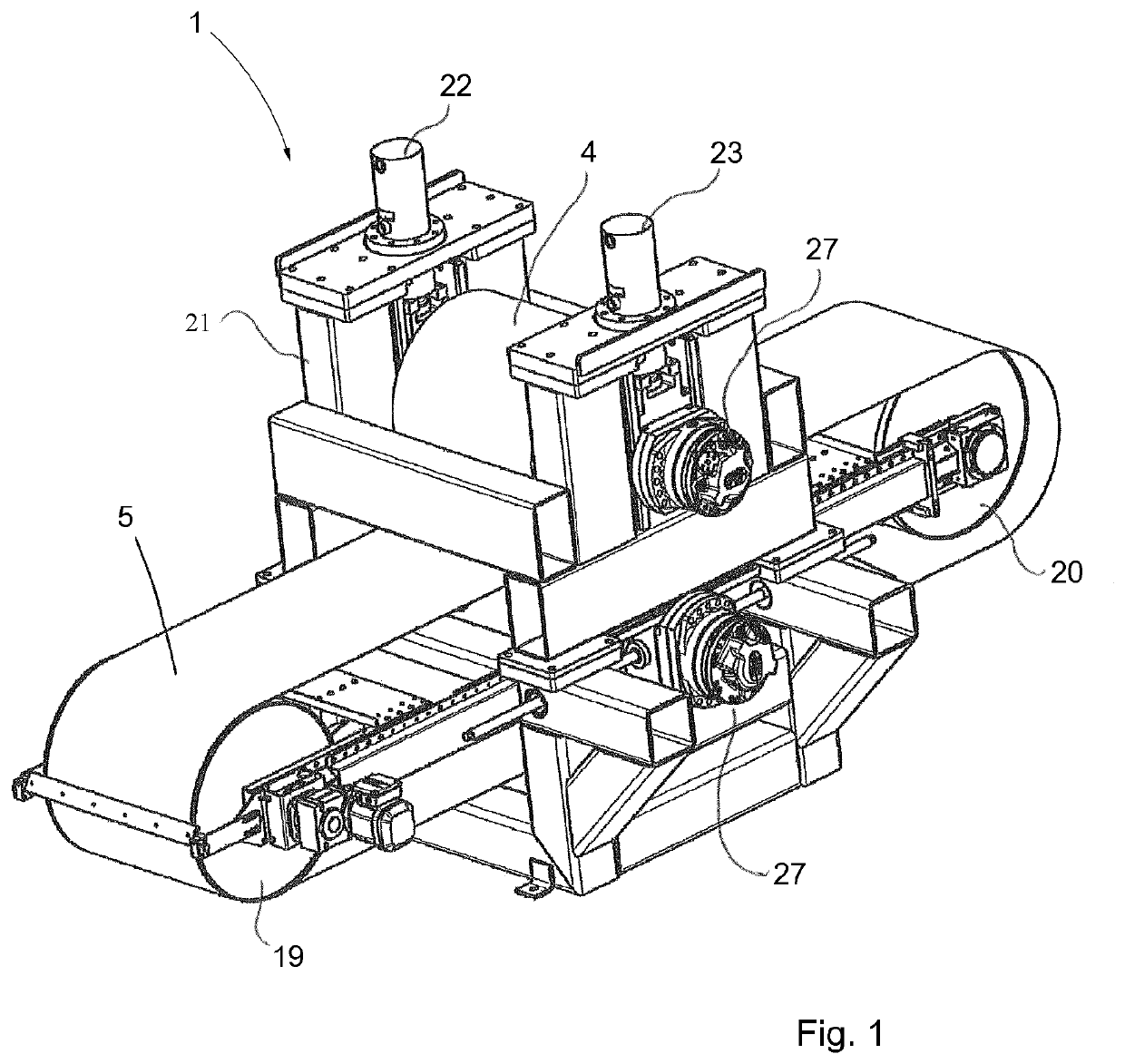
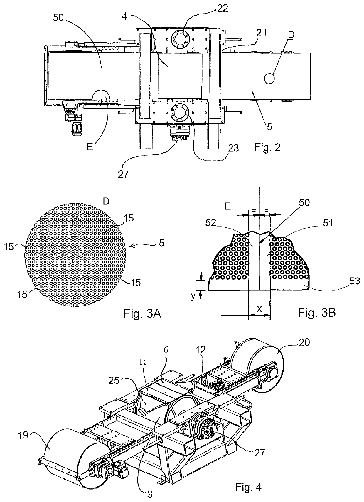
[0039]With reference to FIG. 1, FIG. 2, FIG. 4, FIG. 7, FIG. 8a and FIG. 8b, the invention relates to an apparatus for dewatering wood chips 2. The apparatus 1 comprises a first roll 3 and a second roll 4 that form at least a first nip N1. As best seen in FIG. 7, wood chips 2 are passed into the first nip N1 such that water can be pressed out of the wood chips 2. The rolls 3, 4 may be journalled in a roll stand 21 as shown in FIG. 1 and FIG. 7. As indicated in FIG. 1, actuators 22, 23 (for example hydraulic actuators) may suitable be arranged to force the second roll 4 against the first roll 3 such that the first nip N1 is loaded and wood chips 2 that pass through the first nip N1 will be compressed by the force in the nip. One of the rolls 3, 4 or both rolls 3, 4 may be provided with a drive for driving the roll. In FIG. 1, the reference numeral 27 may indicate a drive for a roll 3, 4 or a connection to a drive for a roll 3, 4.

[0040]Larger wood pieces have previously been cut into ...


PUM


Abstract

An apparatus (1) and a method for dewatering wood material (2). The apparatus (1) includes a first roll (3) and a second roll (4) that form a nip (N i) in which water can be pressed out of the wood chips (2). An endless permeable conveyor (5) is arranged to pass through the nip (Ni) and carry wood chips (2) through the (Ni).

Description

CROSS REFERENCE TO RELATED APPLICATIONS[0001]This application is a 35 U.S.C. § 371 national stage of International Application No. PCT / EP2013 / 067793 filed on Aug. 28, 2013, published in English under PCT Article 21(2), which claims the benefit of priority to Swedish Patent Application No. 1250958-4 filed on Aug. 28, 2012, the disclosures of which are hereby incorporated by reference.FIELD OF THE INVENTION[0002]The present invention relates to an apparatus and a method in which wood chips are dewatered in a nip formed between rolls.BACKGROUND OF THE INVENTION[0003]In order to use wood a source of energy, wood chips can be dewatered and subsequently used as fuel. To remove water from the wood chips, the wood chips may be subjected to heat that causes moisture in the wood chips to evaporate. However, such methods are time-consuming and require large amounts of energy which makes such methods less effective in terms of energy economy. A method which is more economical in terms of energy...

Claims


Application Information

Patent Timeline
Patent Type & Authority Patents(United States)
IPC IPC(8): B30B9/24F26B5/12F26B5/14F26B17/04B30B13/00B30B9/20
CPCF26B17/04B30B9/241F26B5/14B30B13/00B30B9/24B30B9/20B30B9/243F26B5/12F26B2200/24B30B9/262
Inventor SOBOTA, ERNEST STEFAN GEORGKARLSSON, CARL JOHAN INGVAR
Owner COPOLIA COMPANY
Learn More