Reflector clamping member and use thereof

a technology of clamping member and reflector, which is applied in the direction of volume/mass flow measurement, measurement devices, instruments, etc., can solve the problems of high production cost, many of known ultrasonic flow meters may suffer, and the fixation may be relatively complex, so as to reduce the dimensions of the pins. the effect of simple and cost-effectiv

Active Publication Date: 2020-03-17
APATOR MIITORS APS
View PDF7 Cites 0 Cited by
  • Summary
  • Abstract
  • Description
  • Claims
  • Application Information

AI Technical Summary

Benefits of technology

[0008]One advantage of the present invention may be that a relatively robust fixation of the ultrasound reflector to the flow conduit insert may be realized with relatively low-cost parts. Specifically, criteria for the dimensional tolerances may be less strict, thus supporting the use of low-cost parts, or the requirements for long-term deformation may be less strict, also supporting the use of low-cost parts. By realizing a fixation of the ultrasound reflector by means of clamping the ultrasound reflector between the flexible part and the flow conduit insert, the flexible portion can compensate for inaccuracies in the dimensions of the reflector clamping member, the ultrasound reflector and the flow conduit insert. The above advantage may be realized while maintaining a relatively simple assembly setup, since the clamping of the ultrasound reflector may be established by means of the reflector clamping member and the flow conduit insert alone and also by allowing the ultrasound reflector to have a relatively simple design. Thus, by avoiding very complicated assembly from multiple parts, production costs can be kept at a lower level.
[0009]The reflector clamping member should be understood as any device that can clamp an ultrasound reflector to a flow conduit insert according to the present invention. Thus, the reflector clamping device may be understood as for example a clamp or a fixture. In some embodiments, the reflector clamping member may be formed as a plug, a cap or a cover, whereas in other embodiments the reflector clamping member may be devised to merely facilitate fixation of the ultrasound reflector to the flow conduit insert by clamping the ultrasound reflector between the flexible portion and the flow conduit insert.
[0010]Thus, according to the invention it should be understood that by clamping the ultrasound reflector between the flexible portion and the flow conduit insert when the reflector clamping member, the ultrasound reflector, and the flow conduit insert are assembled, the ultrasound reflector is fixated to the flow conduit insert.
[0011]In the present context it should be understood that the term “assembled configuration” is intended to mean that the ultrasound reflector, the reflector clamping member, and the flow conduit insert is assembled to clamp and thus fixate the ultrasound reflector between the flow conduit insert and the flexible portion of the reflector clamping member. When in assembled configuration, a flow conduit insert assembly is formed comprising the ultrasound reflector, the reflector clamping member, and the flow conduit insert.
[0012]The reflector clamping member of the invention is adapted to clamp an ultrasound reflector to a flow conduit insert. The clamp may be devised in various shapes and sized in order to fit corresponding ultrasound reflectors, which ultrasound reflectors may be available with various dimensions according to the particular application. One example of an ultrasound reflector, which is usable with the reflector clamping member of the invention, is an ultrasound reflector for a utility meter, such as a utility water meter. Such ultrasound reflectors may as an example comprises a reflecting surface having a minimum width of between 1 and 20 millimeter, such as between 5 and 15 millimeter. Also, such ultrasound reflectors may as an example have a thickness of between 0.2 and 3 millimeters, such as between 0.5 and 2 millimeters. However, the reflector clamping member of some embodiments may also be used with larger ultrasound reflectors, e.g. for use with the utility grid; and may also in other embodiments be used with even smaller ultrasound reflectors than exemplified above.
[0013]According to the invention, it must be ensured that the flexible portion is adapted to allow contact with the ultrasound reflector, and that the fixation portion is joined with the flexible portion. It should be understood that the flexible portion and the fixation may be joined in various ways. In some embodiments, the reflector clamping member further comprises a joining portion which joins the fixation portion with the flexible portion. Moreover, in other embodiments the flexible portion may be directly joined and connected to the fixation portion. Even further, the flexible portion or parts thereof may be provided as an adjacent part in abutment with the fixation portion and / or the joining portion and may thus be removable therefrom. Even further, it must also be ensured that the flexible portion is adapted for supporting at least one side of the ultrasound reflector so as to clamp the ultrasound reflector between the flexible portion and the flow conduit insert when the reflector clamping member, the ultrasound reflector, and the flow conduit insert are assembled, i.e. assembled to form a flow conduit insert assembly.

Problems solved by technology

When fixating the ultrasound reflectors to an insert to be positioned in the flow conduit, i.e. where the ultrasound passes through the fluid, such fixation may be relatively complex.
However, many of known ultrasonic flow meters may suffer from drawbacks such as expensive production, inaccurate fixation of ultrasound reflectors, or problems with fluctuating flow measurements or decreasing accuracy of flow measurements.

Method used


Image

  • Reflector clamping member and use thereof
  • Reflector clamping member and use thereof
  • Reflector clamping member and use thereof

Examples


Embodiment Construction

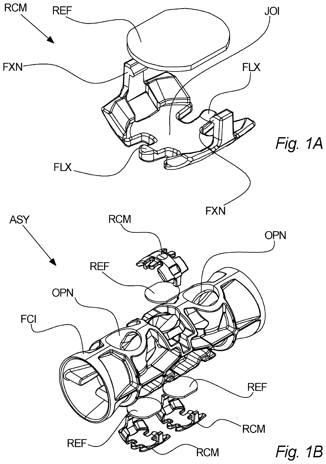
[0096]Referring to FIGS. 1A and 1B, a reflector clamping member RCM according to an embodiment of the invention is illustrated. In more detail, FIG. 1A shows a perspective view of a reflector clamping member RCM with a corresponding ultrasound reflector REF, with a distance between the two. Furthermore, FIG. 1B shows an exploded perspective view of a flow conduit insert assembly ASY comprising the reflector claiming members RCM shown in FIG. 1A.

[0097]The reflector clamping member RCM shown on FIG. 1A is adapted to fixate an ultrasound reflector REF to a flow conduit insert FCI of an ultrasonic flow meter UFM. The flow conduit insert FCI is shown on FIG. 1B. When the reflector clamping member(s) RCM, the ultrasound reflector(s) REF and the flow conduit insert FCI are assembled, they form a flow conduit insert assembly ASY, which may thus be inserted into a flow conduit FC of an ultrasonic flow meter UFM. An example thereof is illustrated on FIG. 5 and the corresponding description.

[0...


PUM


Abstract

A reflector clamping member (RCM) for fixating an ultrasound reflector (REF) to a flow conduit insert (FCI) of an ultrasonic flow meter (UFM) is disclosed, the reflector clamping member (RCM) comprising a fixation portion (FXN) for fixating the reflector clamping member (RCM) to the flow conduit insert (FCI) and a flexible portion (FLX) for contacting the ultrasound reflector (REF), wherein the flexible portion (FLX) is adapted for supporting at least one side of the ultrasound reflector (REF) so as to clamp the ultrasound reflector (REF) between the flexible portion (FLX) and the flow conduit insert (FCI) when the reflector clamping member (RCM), the ultrasound reflector (REF), and the flow conduit insert (FCI) are assembled. Also, a flow conduit insert assembly (ASY) comprising such reflector clamping member (RCM), an ultrasonic flow meter (UFM) comprising such reflector clamping member (RCM), and a method of fixating an ultrasound reflector (REF) to a flow conduit insert (FCI) are disclosed.

Description

CROSS REFERENCE TO RELATED APPLICATIONS[0001]This application is a U.S. National Phase Application of International Application No. PCT / DK2016 / 050182, filed Jun. 14, 2016, which is hereby incorporated by reference in its entirety.FIELD OF INVENTION[0002]The present invention relates to the field of ultrasonic flow metering, particularly to a reflector clamping member for fixating an ultrasound reflector to a flow conduit insert of an ultrasonic flow meter according to claim 1 and use of such ultrasonic flow member.BACKGROUND[0003]Different solutions for fixating ultrasound reflectors in ultrasonic flow meters are known. When fixating the ultrasound reflectors to an insert to be positioned in the flow conduit, i.e. where the ultrasound passes through the fluid, such fixation may be relatively complex. However, many of known ultrasonic flow meters may suffer from drawbacks such as expensive production, inaccurate fixation of ultrasound reflectors, or problems with fluctuating flow mea...

Claims


Application Information

Patent Timeline
Patent Type & Authority Patents(United States)
IPC IPC(8): G01F1/66G01F15/14G01F15/18
CPCG01F15/14G01F1/662G01F15/18
Inventor PRICE, JAMES EDWARD
Owner APATOR MIITORS APS
Why Eureka
Try Eureka