Dumbbell with rotating grip

a technology of rotating grip and dumbbell, which is applied in the field of dumbbell with rotating grip, can solve the problems of affecting the rotational grip of prior art dumbbells and not providing premium feel, so as to avoid injuries to the human wrist and elbow join

Active Publication Date: 2022-03-01
ELEIKO GRP AB
View PDF18 Cites 0 Cited by
  • Summary
  • Abstract
  • Description
  • Claims
  • Application Information

AI Technical Summary

Benefits of technology

[0009]By such an arrangement, a high end dumbbell with an ergonomic and user friendly design is achieved. The grip is as mentioned above, rotatable relative to the shaft and the dumbbell heads, and thereby the design of the dumbbell is gentle to the wrist. The overall design enables the use of a thinner grip, which fits most users and is able to use for all weights from light weights to heavy weights. Since the shaft is fixedly connected to the dumbbell heads, any shock force hitting the dumbbell, for example by a sudden drop of the dumbbell, only affects the dumbbell heads and the shaft, but hardly not at all, the rotating grip. This is far better than existing dumbbells and enables a longer life time of the dumbbell, and with remained high end feeling of the rotating grip. The rotating grip of prior art dumbbells is normally negatively affected by shock forces and the like, which is normal in the daily use of dumbbells, since there normally is contact between the shaft and the rotating grip in known solutions. Since the rotating grip is fixedly arranged to the inner rings of the ball bearings in the present solution, and the shaft is fixedly arranged to the dumbbell heads, the shaft as well as the grip may be rather thin, preferably with only a minimum of space between inside of the grip and the outside of the shaft. Thereby, the outside diameter of the grip may be for example 38 mm, and thereby fit most users. Prior art premium solutions, designed for use at all kinds of weights from say 5 kg up to 68 kg, have grips with outer diameter of about 50 mm, since the design is made such as the bearing is arranged between the grip and the shaft and sometimes with a rather thick shaft. In some prior art solutions with thin shaft design, the rotating grip is fitted around the shaft with a slide bearing between the grip and the shaft. Such solutions do not provide a premium feel and tends to be impaired over time since the slide bearing is worn out. With the inventive rotating, thin-grip design of the present dumbbell, the premium feel is not impaired over time and fits all dumbbells from low weights to high weights, even up to 68 kg which is not at hand in prior art dumbbells.
[0010]According to an embodiment, the inner ring of the first ball bearing and the inner ring of the second ball bearing respectively has an inner diameter which substantially corresponds with the outer diameter of the grip, such as the grip is fixedly arranged with its first end inside the inner ring of the first ball bearing and with its second end inside the inner ring of the second ball bearing. By the corresponding dimensions of the inner diameter of the ball bearings and the outer diameter of the grip, it is possible to get a robust fixation of the grip inside the bearings. And by fixedly fitting the ends of the grip inside the inner rings of the ball bearings and by that the inner diameter of the grip is slightly greater than the outer diameter of the shaft, the grip is not in contact with the shaft. Thereby, shock forces from a sudden drop of the dumbbell or a careless handling of the same, are taken care of by the dumbbell heads and the shaft and is not affecting the rotating grip that much. This is a far better solution compared to prior art.
[0011]According to an embodiment, the inner side of the first dumbbell head comprises a first cavity, which is centered around the longitudinal axis of the shaft. In the same way, the inner side of the second dumbbell head comprises a second cavity, which also is centered around the longitudinal axis of the shaft. The first cavity has an outer diameter which substantially corresponds with an outer diameter of the first ball bearing and the second cavity has an outer diameter which substantially corresponds with an outer diameter of the second ball bearing. This enables that the first ball bearing may be arranged in the first cavity and the second ball bearing may be arranged in the second cavity. To arrange the ball bearings into cavities in the dumbbell heads makes a smooth and nice design which doesn't impact on the grip and the space available for the hand.
[0012]According to an embodiment, the first dumbbell head is fixedly connected to the first end of the shaft by press fitting, and the second dumbbell head is fixedly connected to the second end of the shaft by press fitting. Thereby, a robust fixation of the dumbbell heads to the shaft is achieved, which gains power absorption from hits and shock forces and thus enables a longer life time compared to prior art.
[0018]According to an embodiment, the ball bearings are sealed low friction ball bearings. Thereby, the rotation of the grip is very easy, and the impact of the wrist is minimized. At the same time, the seal prevents dirt from entering into the ball bearing, which facilitates a simple and cost effective design where the ball bearing may have an exposed side facing the grip, without any cover plate or the like, thanks to the seal.

Problems solved by technology

The rotating grip of prior art dumbbells is normally negatively affected by shock forces and the like, which is normal in the daily use of dumbbells, since there normally is contact between the shaft and the rotating grip in known solutions.
Such solutions do not provide a premium feel and tends to be impaired over time since the slide bearing is worn out.

Method used


Image

  • Dumbbell with rotating grip
  • Dumbbell with rotating grip

Examples


Embodiment Construction

[0027]Briefly described, a high end dumbbell with an ergonomic and user friendly design with a long life time is disclosed.

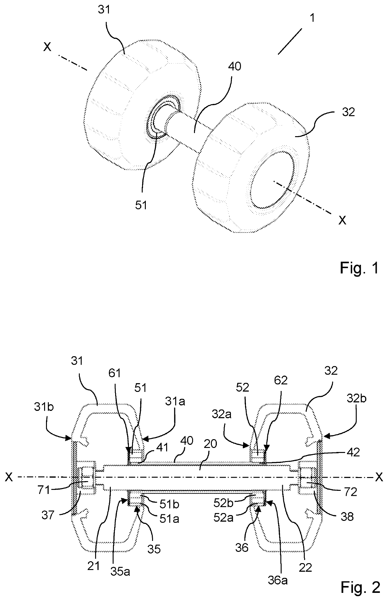
[0028]FIG. 1 shows a perspective view of a dumbbell 1 according to the invention. The dumbbell 1 comprises a first dumbbell head 31 and a second dumbbell head 32 arranged on a respective side of a grip 40. The grip 40 is in turn arranged around a shaft 20 (not visible in FIG. 1), which shaft 20 extends along a longitudinal axis X-X. Visible in the figure is also a first ball bearing 51. The constructional design of the dumbbell 1 will be further explained below.

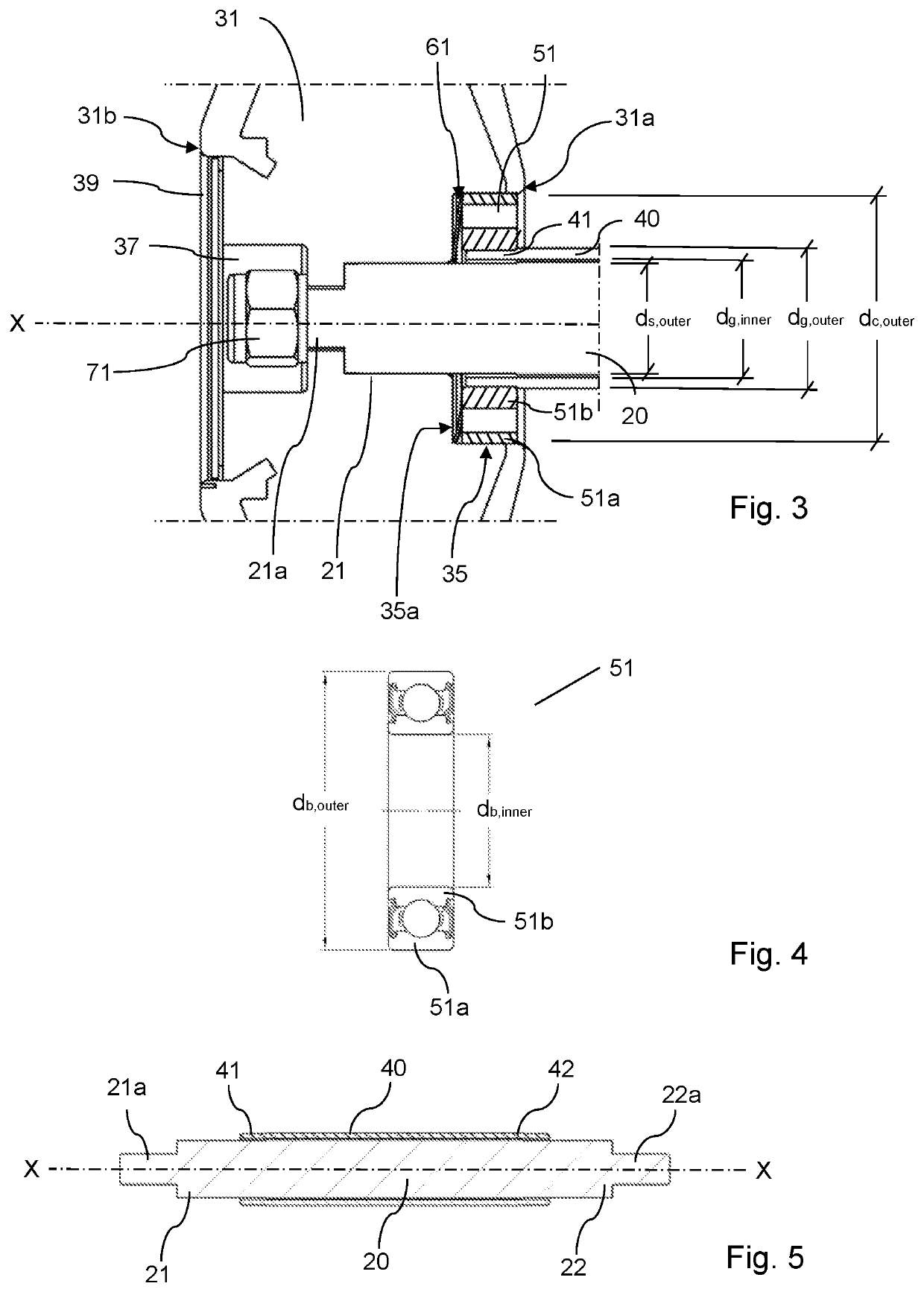
[0029]FIG. 2 shows a longitudinal cross section of the dumbbell 1 of FIG. 1. As mentioned above, the dumbbell 1 comprises the shaft 20. The shaft 20 has a cross-sectional dimension ds,outer, and extends, as mentioned above, along a longitudinal axis X-X (see also FIGS. 3 and 5). The shaft is made of steel with a yield strength between 800-1000 N / mm2 and a tensile strength of 1000-1400 N / mm2.

[0030]The firs...


PUM


Abstract

A dumbbell having a shaft, first and second dumbbell heads, respectively fixedly connected to first and second ends of the shaft, a tube-shaped hollow grip rotatably arranged around the shaft having first and second ends. An inner diameter of the grip is greater than an outer cross-sectional dimension of the shaft. The dumbbell further having a first ball bearing and a second ball bearing, wherein an outer ring of the first ball bearing is connected to the first dumbbell head, and an inner ring of the first ball bearing is fixedly arranged to the first end of the hollow grip, and an outer ring of the second ball bearing is connected to the second dumbbell head, and an inner ring of the second ball bearing is fixedly arranged to the second end of the hollow grip.

Description

RELATED APPLICATION DATA[0001]This application claims the benefit of Swedish Patent Application No. 1851398-6, filed on Nov. 9, 2018, the disclosure of which is incorporated herein by reference in its entirety.TECHNICAL FIELD[0002]The invention considers a dumbbell with a rotating grip.BACKGROUND ART[0003]Different kinds of dumbbells with a rotating grip or rotating weights are known, but they have a number of drawbacks.[0004]One solution is presented in document KR20120005422U, which describes a dumbbell with rotatable weights. The dumbbell has a grip inside which a rotatable shaft extends, and the weights are attached to the rotatable shaft. The object of the invention is to provide vibrations in the dumbbell, which vibrations affects muscles in the body. The vibrations are achieved by that the weights rotates while the handle is moved to the right and left respectively forwards and backwards. The problem solved by this solution is another than the present invention solves, and th...

Claims


Application Information

Patent Timeline
Patent Type & Authority Patents(United States)
IPC IPC(8): A63B21/072A63B21/00
CPCA63B21/0726A63B21/4035A63B21/4043A63B21/0728A63B21/072
Inventor SIMONSON, ROYSCHOUGH, CAMILLA
Owner ELEIKO GRP AB
Why Eureka
Try Eureka