Accessory device with snap feature

a technology of accessory devices and snap features, which is applied in the direction of medical devices, infusion syringes, drugs and medications, etc., can solve the problems of inability to build-in electronic data acquisition functionality in the device itself, inability to easily upload logged information to a computer for data processing, and misleading bases, etc., to achieve robust fixation

Active Publication Date: 2020-03-31
NOVO NORDISK AS
View PDF35 Cites 0 Cited by
  • Summary
  • Abstract
  • Description
  • Claims
  • Application Information

AI Technical Summary

Benefits of technology

[0012]By this arrangement, using one or more separate wires, the snap-on force can be optimized to achieve both secure attachment and ease of use just as the wire material can be chosen so as to retain its strength over the lifetime of the add-on device thereby providing a robust fixation.
[0013]At least one individual snap lock may further comprise a pair of circumferentially arranged support structures serving as fulcrum points for the wire portion when the wire portion is moved laterally by the drug delivery device lateral projection when the coupling portion is inserted axially in the bore. By allowing the position of the fulcrum points to be determined during development varying degrees of pull-off / put-on forces can be obtained. In contrast to wire material which normally is offered with standard diameters, the provision of pairs of fulcrum points allows the snap lock characteristics to be finely adjusted during the development by varying the distance between the points for a given wire diameter. The wire material will typical be a metal composition.
[0015]The ring-formed wire locking member and the bore may be configured such that the ring-formed locking member can be inserted in the bore and snap non-releasable in place, i.e. the locking member cannot be removed without using a tool and / or without damaging the structures. In this way the elastic properties of the wire is utilized during both manufacture and subsequent use. Alternatively, a ring-formed member may be mounted in the cylindrical bore and adapted to hold the ring-formed locking member non-releasable in place.
[0027]The snap members may be generally ring-formed, this allowing the ring-formed snap members and the bore to be configured such that the ring-formed snap member can be inserted in the bore and snap non-releasable in place. In this way a given assembled main unit can be used for all versions of a secondary unit, this allowing coding to take place after (almost) final assembly in a cost-effective way.

Problems solved by technology

However, such logs are normally kept in handwritten notebooks, from the logged information may not be easily uploaded to a computer for data processing.
A missing or erroneous record in the log results in a misleading picture of the injection history and thus a misleading basis for the medical personnel's decision making with respect to future medication.
The latter devices are to be discarded after being emptied and so inexpensive that it is not cost-effective to build-in electronic data acquisition functionality in the device it-self.

Method used


Image

  • Accessory device with snap feature
  • Accessory device with snap feature
  • Accessory device with snap feature

Examples


Embodiment Construction

[0042]When in the following terms such as “upper” and “lower”, “right” and “left”, “horizontal” and “vertical” or similar relative expressions are used, these only refer to the appended figures and not necessarily to an actual situation of use. The shown figures are schematic representations for which reason the configuration of the different structures as well as their relative dimensions are intended to serve illustrative purposes only. When the term member or element is used for a given component it generally indicates that in the described embodiment the component is a unitary component, however, the same member or element may alternatively comprise a number of sub-components just as two or more of the described components could be provided as unitary components, e.g. manufactured as a single injection moulded part. The term “assembly” does not imply that the described components necessarily can be assembled to provide a unitary or functional assembly during a given assembly pro...


PUM


Abstract

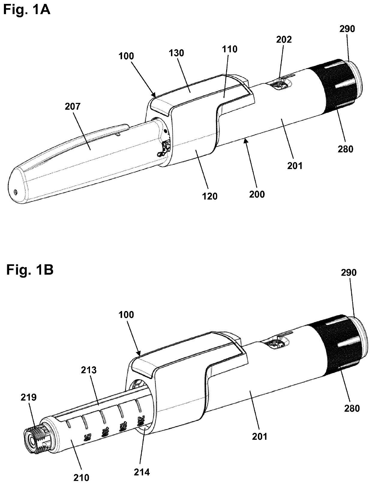
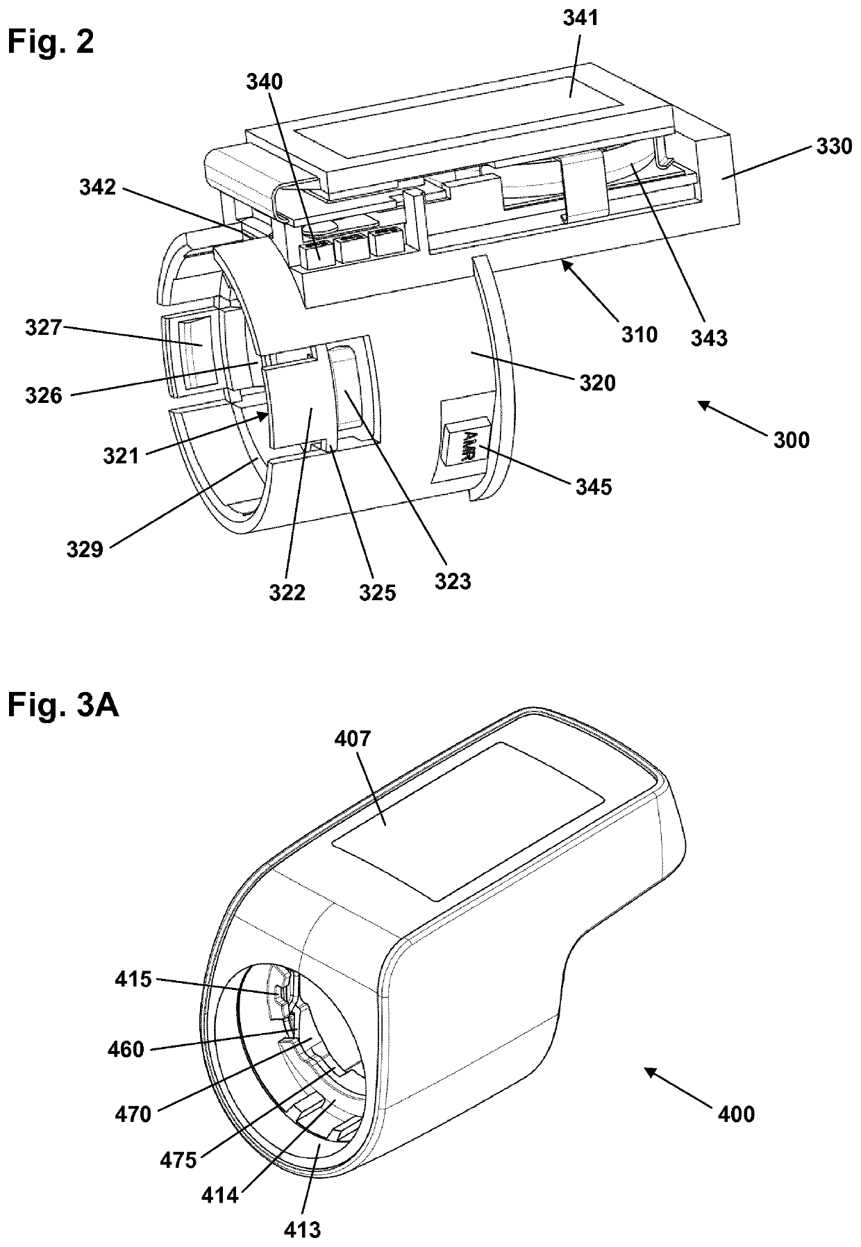
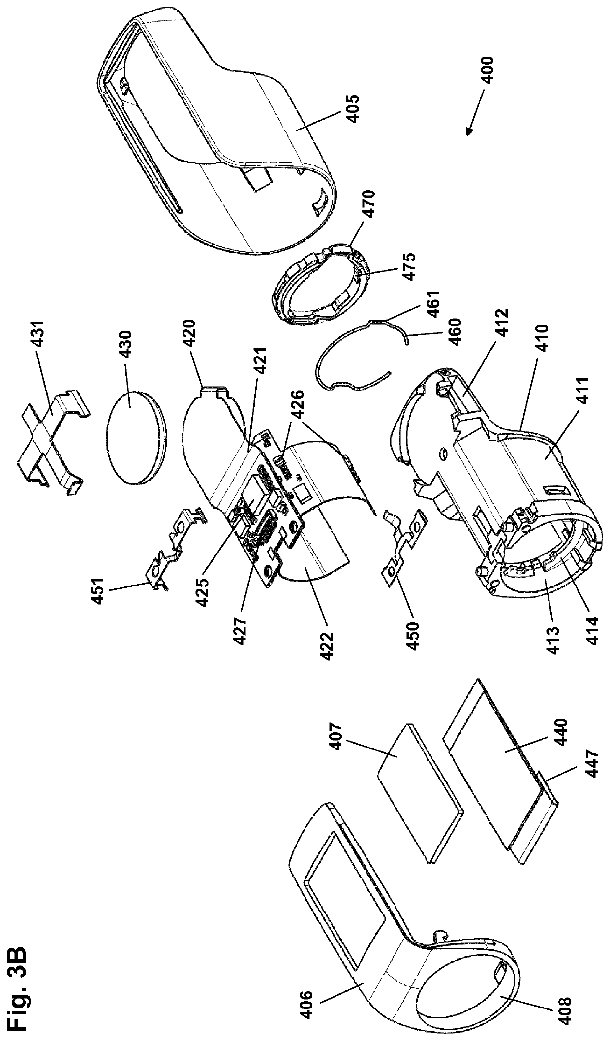
A logging device adapted to be attached to a pen drug delivery device (210) and capture a property value related to the dose amount of drug expelled from the drug delivery device during an expelling event, the logging device comprising a bore in which a snap lock with a flexible wire portion is arranged circumferentially in the bore, the wire being adapted to be moved laterally by a projection on the pen device and subsequently snap inwardly when the pen device is inserted axially in the bore. In this way an axial snap lock is provided between the logging device and the drug delivery device.

Description

CROSS-REFERENCE TO RELATED APPLICATIONS[0001]This application is a 35 U.S.C. § 371 National Stage application of International Application PCT / EP2015 / 069396 (published as WO 2016 / 030348), filed Aug. 25, 2015, which claims priority to European Patent Application 14182145.4, filed Aug. 25, 2014, and priority to European Patent Application 14191476.2, filed Nov. 3, 2014; the contents of which are incorporated herein by reference.[0002]The present invention generally relates to medical devices for which the generation, collecting and storing of data are relevant. In specific embodiments the invention relates to devices and systems for capturing and organizing drug delivery dose data in an efficient and user-friendly way.BACKGROUND OF THE INVENTION[0003]In the disclosure of the present invention reference is mostly made to drug delivery devices comprising a threaded piston rod driven by a rotating drive member, such devices being used e.g. in the treatment of diabetes by delivery of insu...

Claims


Application Information

Patent Timeline
Patent Type & Authority Patents(United States)
IPC IPC(8): A61M5/315A61M5/20A61M5/24G16H20/17
CPCA61M5/31568A61M5/24G16H20/17A61M5/20A61M2205/6045A61M2205/6036A61M2205/33
Inventor JAKOBSEN, NIKOLAJ EUSEBIUSMCLOUGHLIN, IAN
Owner NOVO NORDISK AS
Why Eureka
Try Eureka