Radar level gauge system with low reflection spacer arrangement

a technology of spacer arrangement and radar level gauge, which is applied in the direction of instruments, engine lubrication, liquid/fluent solid measurement, etc., can solve the problems of affecting the measurement quality and disturbing the filling level measurement, and achieve the effect of less disturban

Active Publication Date: 2020-03-17
ROSEMOUNT TANK RADAR
View PDF7 Cites 2 Cited by
  • Summary
  • Abstract
  • Description
  • Claims
  • Application Information

AI Technical Summary

Benefits of technology

[0010]In view of the above, a general object of the present invention is to provide an improved guided wave radar level gauge system with a probe comprising a first probe conductor and a second probe conductor, in particular a guided wave radar level gauge system with less disturbance from spacers arranged to control the positional relation between the first and second probe conductors.
[0019]The present invention is based on the realization that spacers or spacer arrangements may be formed in such a way that reflections from different parts of the spacers or spacer arrangements interact to provide a lower total reflection in the relevant frequency range. This may open up for the use of a greater variety of spacer materials with suitable mechanical and / or thermal properties, such as ceramics. In addition the use of so-called FMCW techniques for guided wave radar systems with two-conductor probes may be facilitated, since the spacers or spacer arrangements according to embodiments of the present invention can be tuned to advantageous frequency ranges for FMCW sensing.

Problems solved by technology

However, ceramic spacers exhibit stronger reflections, which may be detrimental to the measurement quality.
Further, it may be desirable to use higher frequencies (such as 1-2 GHz) for the transmit signal, which may make the measurements significantly more sensitive to spacer reflections, so that even the use of spacers made of a low-reflection material (such as PTFE) may disturb the filling level measurements.

Method used


Image

  • Radar level gauge system with low reflection spacer arrangement
  • Radar level gauge system with low reflection spacer arrangement
  • Radar level gauge system with low reflection spacer arrangement

Examples


Embodiment Construction

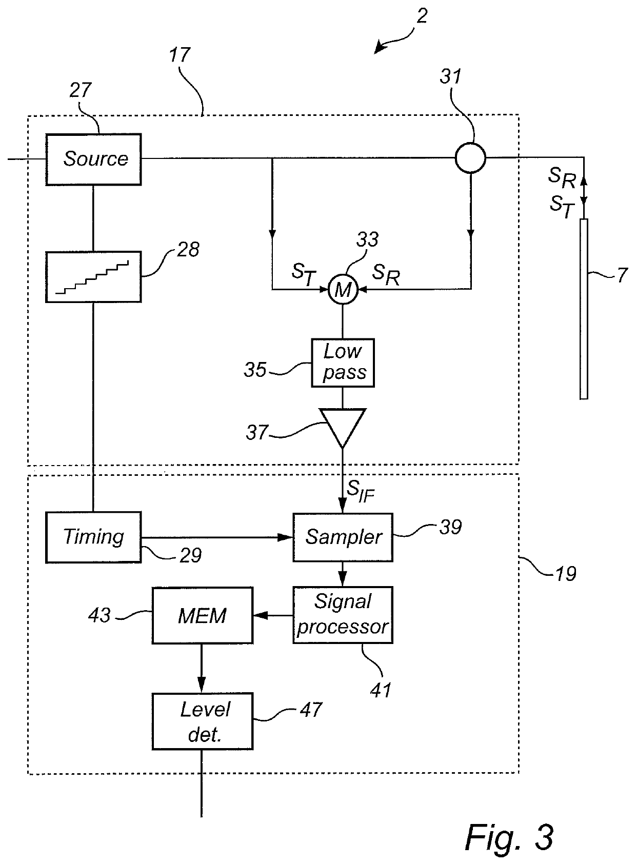
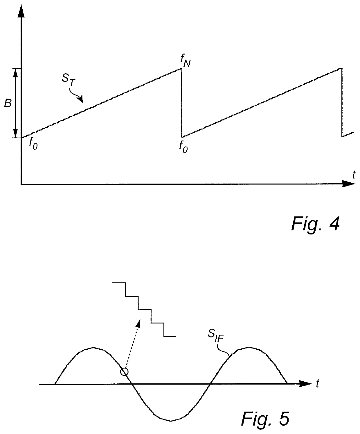
[0036]In the present detailed description, various embodiments of the present invention are mainly discussed with reference to an FMCW-type radar level gauge system.

[0037]It should be noted that this by no means limits the scope of the present invention, which also covers a pulsed radar level gauge system.

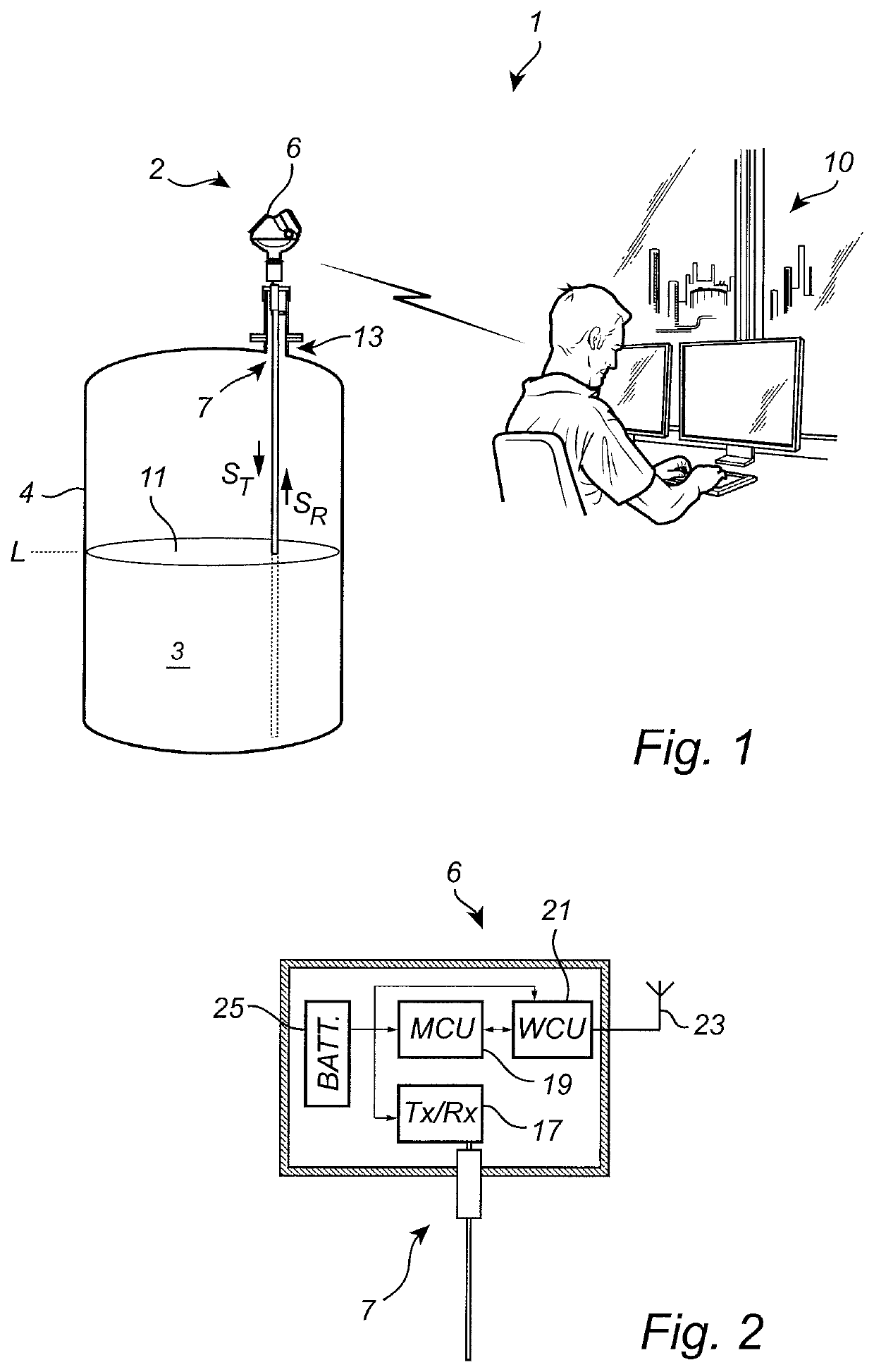
[0038]FIG. 1 schematically shows a level measuring system 1 comprising a radar level gauge system 2 according to an example embodiment of the present invention, and a host system 10 illustrated as a control room.

[0039]The radar level gauge system 2 of GWR (Guided Wave Radar) type is installed at a tank 4 having a tubular mounting structure 13 (often referred to as a “nozzle”) extending substantially vertically from the roof of the tank 4.

[0040]The radar level gauge system 2 is installed to measure the filling level of a product 3 in the tank 4. The radar level gauge system 2 comprises a measuring unit 6 and a propagation device in the form of probe 7 extending from the measuring un...


PUM


Abstract

A radar level gauge system comprising a transceiver; a multi-conductor probe comprising a first probe conductor and a second probe conductor extending together from an upper probe end to a lower probe end; a plurality of spacer arrangements distributed along the multi-conductor probe; and processing circuitry for determining the filling level. Each spacer arrangement in the plurality of spacer arrangements comprises a first spacer member configured to reflect a transmit signal as a first spacer reflection signal having a first amplitude; and a second spacer member configured to reflect the transmit signal as a second spacer reflection signal having a second amplitude. The first spacer member and the second spacer member are arranged along the multi-conductor probe so that the first and second spacer reflection signals interact to provide a combined spacer reflection signal having an amplitude lower than each of the first amplitude and the second amplitude.

Description

TECHNICAL FIELD OF THE INVENTION[0001]The present invention relates to a radar level gauge system with a probe comprising a first probe conductor and a second probe conductor, and a plurality of spacers or spacer arrangements for controlling a positional relationship between the first probe conductor and the second probe conductor.TECHNICAL BACKGROUND[0002]Radar level gauge (RLG) systems are in wide use for determining filling levels in tanks. An electromagnetic transmit signal is generated by a transceiver and propagated towards the surface of the product in the tank, and an electromagnetic reflection signal resulting from reflection of the transmit signal at the surface is received by the transceiver.[0003]Based on the transmit signal and the reflection signal, the distance to the surface of the product can be determined.[0004]Most radar level gauge systems on the market today are either so-called pulsed radar level gauge systems that determine the distance to the surface of the p...

Claims


Application Information

Patent Timeline
Patent Type & Authority Patents(United States)
IPC IPC(8): G01F23/284
CPCG01F23/284
Inventor EDVARDSSON, OLOV
Owner ROSEMOUNT TANK RADAR
Why Eureka
Try Eureka