Ball rotational direction detecting system

a detection system and rotational direction technology, applied in the direction of acceleration measurement in multiple dimensions, acceleration measurement using interia forces, instruments, etc., can solve the problem of large measurement of an apparatus, and achieve the effect of simple configuration

Active Publication Date: 2020-03-17
AICHI STEEL
View PDF19 Cites 0 Cited by
  • Summary
  • Abstract
  • Description
  • Claims
  • Application Information

AI Technical Summary

Benefits of technology

The present invention introduces a system that can detect the orientation and direction of rotation of a baseball or softball in flight. This information can be used to improve the pitching form and grip of the player. The system utilizes geomagnetism, acceleration, and magnetic dipoles to determine the orientation of the rotation axis and the rotational direction of the ball with respect to the direction of travel and gravity. Overall, this patented technology provides a simple and efficient means to detect the ball's movement in flight.

Problems solved by technology

In such a case, although it is possible to measure how a ball rotates based on images captured by a high-speed camera or the like, there is still a problem in that such measurement makes an apparatus large-scale.

Method used


Image

  • Ball rotational direction detecting system
  • Ball rotational direction detecting system
  • Ball rotational direction detecting system

Examples


embodiment 1

(Embodiment 1)

[0061]An embodiment of a ball rotational direction detecting system will be described with reference to FIG. 1 to FIG. 7.

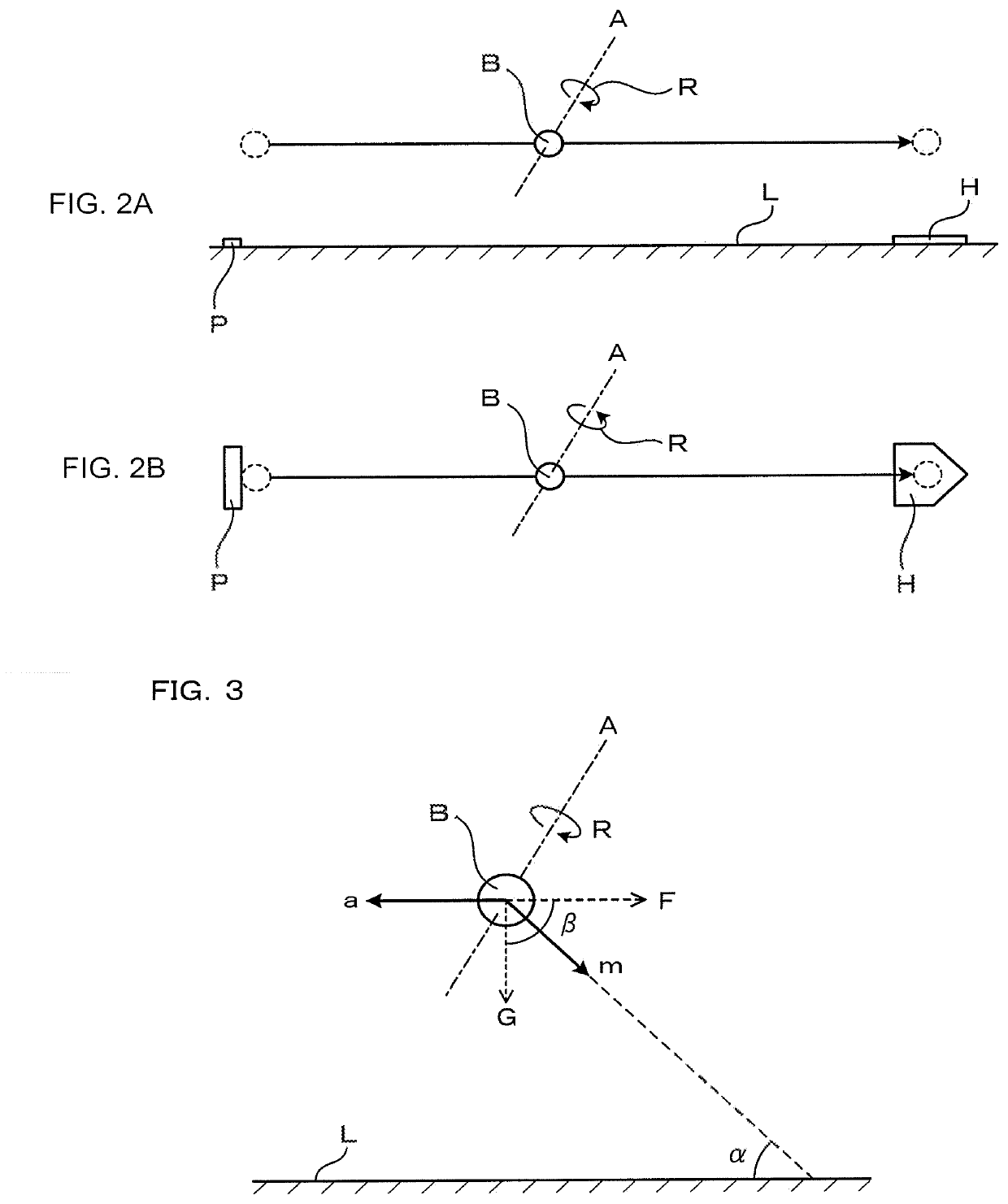
[0062]A ball rotational direction detecting system 1 according to the present embodiment is a system that detects, as illustrated in FIG. 2A, FIG. 2B and FIG. 3, the orientation of a rotation axis A and rotational direction R of a ball B moving in midair, with respect to a traveling direction F of the ball B and a gravity direction G.

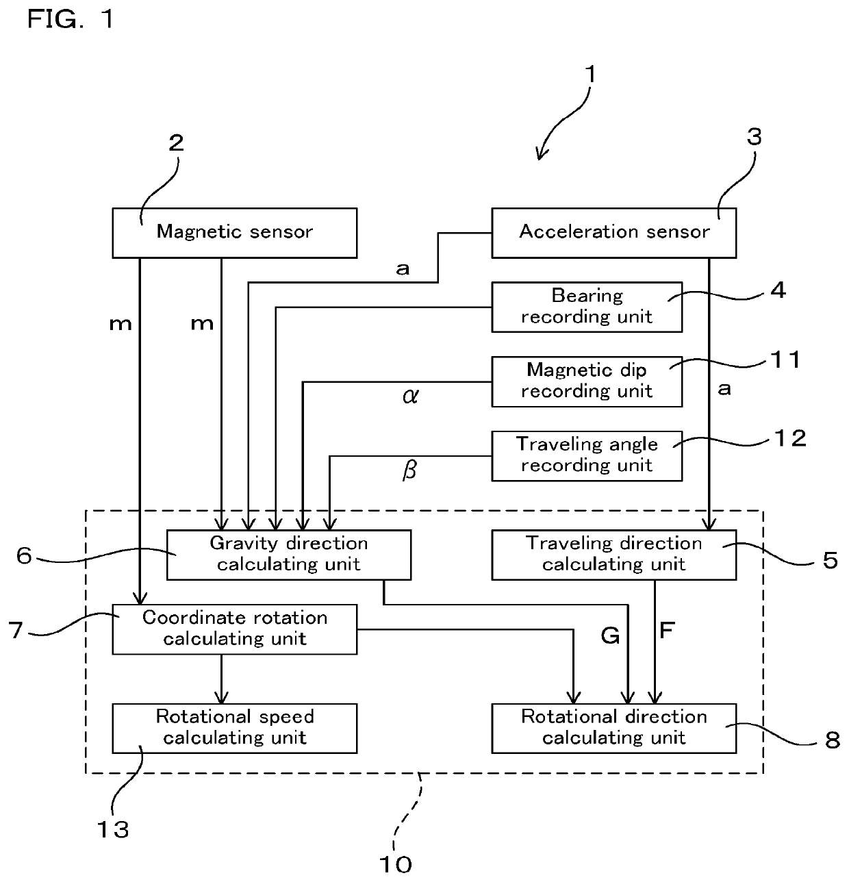
[0063]As illustrated in FIG. 1, the ball rotational direction detecting system 1 includes a magnetic sensor 2, an acceleration sensor 3, a bearing recording unit 4, a magnetic dip recording unit 11, and a calculating unit 10.

[0064]As illustrated in FIG. 4, the magnetic sensor 2 detects a geomagnetism vector m in a ball coordinate system CB, which is a three-axis orthogonal coordinate system fixed in the ball B. The acceleration sensor 3 detects an acceleration vector a in the ball coordinate system CB.

[0065]The bearing r...

embodiment 2

(Embodiment 2)

[0113]The present embodiment is, as illustrated in FIG. 8 to FIG. 10, an embodiment of a ball rotational direction detecting system 1 that further includes a bearing calculating unit 14 that calculates the moving bearing of a ball.

[0114]That is, the bearing calculating unit 14 calculates a moving bearing PH based on the geomagnetism vector m detected by the magnetic sensor 2 with a ball B brought to a standstill in a predetermined posture.

[0115]Here, the term “predetermined posture” means, as illustrated in FIG. 9 and FIG. 10, a posture in which a first specific region B1 and a second specific region B2, which lie on the surface of a ball B and point in directions orthogonal to each other, are made to point in the moving bearing PH and a vertically upward direction.

[0116]The first specific region B1 and the second specific region B2 can serve as, for example, external visible marks on the surface of the ball B. The relation between the first specific region B1 and the ...

embodiment 3

(Embodiment 3)

[0124]The present embodiment is, as illustrated in FIG. 11, an embodiment of a ball rotational direction detecting system 1 further including a magnetic dip calculating unit 15 that calculates a magnetic dip α.

[0125]The magnetic dip calculating unit 15 calculates the magnetic dip α with a ball B brought to a standstill, based on the acceleration vector a detected by the acceleration sensor 3 and the geomagnetism vector m detected by the magnetic sensor 2.

[0126]As illustrated in FIG. 12, in the state where the ball B is brought to a standstill, the direction of the acceleration vector a detected by the acceleration sensor 3 is also the gravity direction G. Therefore, detecting both this acceleration vector a and the geomagnetism vector m leads to the specification of an angle formed by the gravity direction G and the direction of the geomagnetism vector m, thereby in turn leading to the specification of an angle of the geomagnetism vector m with respect to a level surfa...


PUM

PropertyMeasurementUnit
magnetic dips αaaaaaaaaaa
βaaaaaaaaaa
angleaaaaaaaaaa

Abstract

A ball rotational direction detecting system includes a magnetic sensor that is fixed in a ball, an acceleration sensor, a bearing recording unit that records a moving bearing, a magnetic dip recording unit that records a magnetic dip α of geomagnetism, and a calculating unit. The calculating unit calculates the orientation of the rotation axis and the rotational direction of the ball with respect to a traveling direction F and a gravity direction G of the ball, based on a geomagnetism vector m, an acceleration vector a, the moving bearing, the magnetic dip α, and time variations in the geomagnetism vector m or the acceleration vector a.

Description

CROSS-REFERENCE TO RELATED APPLICATION[0001]The present application claims priority under 35 U.S.C. § 119 to Japanese Application No. 2016-044558, filed on Mar. 8, 2016, entitled “BALL ROTATIONAL DIRECTION DETECTING SYSTEM.” The contents of this application are incorporated herein by reference in their entirety.BACKGROUND OF THE INVENTION[0002]Field of the Invention[0003]The present invention relates to a ball rotational direction detecting system that detects the orientation of the rotation axis and the rotational direction of a ball moving in midair with respect to the traveling direction and the gravity direction of the ball.[0004]Description of the Related Art[0005]For example, JP-A-2014-160025 discloses a rotational speed detecting device that detects the rotational speed of a ball moving in midair such as a ball thrown by a baseball pitcher. This rotational speed detecting device is configured so as to be able to calculate the rotational speed of the ball moving in midair base...

Claims


Application Information

Patent Timeline
Patent Type & Authority Patents(United States)
IPC IPC(8): G01V15/00G01P15/08G01P15/18
CPCG01P15/0891G01V15/00G01P15/18
Inventor YAMAMOTO, MICHIHARU
Owner AICHI STEEL
Why Eureka
Try Eureka