Assembly screw for assembling two horology components

a technology screws, which is applied in the field of assembly screws for assembling two horology components, can solve the problems of complex aftersales service operations, difficult solutions in practice, and high risk of unwanted unscrewing of screws, and achieves simple and reliable solutions. the effect of reducing the contact pressur

Active Publication Date: 2020-03-24
ROLEX SA
View PDF12 Cites 1 Cited by
  • Summary
  • Abstract
  • Description
  • Claims
  • Application Information

AI Technical Summary

Benefits of technology

[0007]More specifically, one object of the invention is to propose a simpler and more reliable solution for the pivoting assembly of two horology components.
[0008]To that end, the invention hinges on an assembly screw for the pivoting attachment of at least two horology components in a position of assembly, the assembly screw comprising at least one guide portion allowing one of the horology components to pivot, and at least one threaded portion allowing it to be fixed to another horology component, wherein this screw comprises a shoulder intended to come into abutment against this other horology component and a zone of lower mechanical rigidity to reduce the contact pressure applied at the shoulder of the assembly screw when the horology components are in the position of assembly.

Problems solved by technology

An assembly of this type is exposed to a risk of unwanted unscrewing.
This problem, well known to watchmakers, is caused by the repeated movements of the links relative to one another while the bracelet is being worn, or by shoks.
Such a solution is tricky in practice because it is necessary to master the correct quantity of adhesive.
Aftersales service operations are also complex.
Such a solution entails the assembly of several components, which requires a relatively lengthy assembly time.
Furthermore, because the clamping force applied by the cannon to the screw has to be high, assembly and / or disassembly operations prove to be difficult.

Method used


Image

  • Assembly screw for assembling two horology components
  • Assembly screw for assembling two horology components

Examples


Embodiment Construction

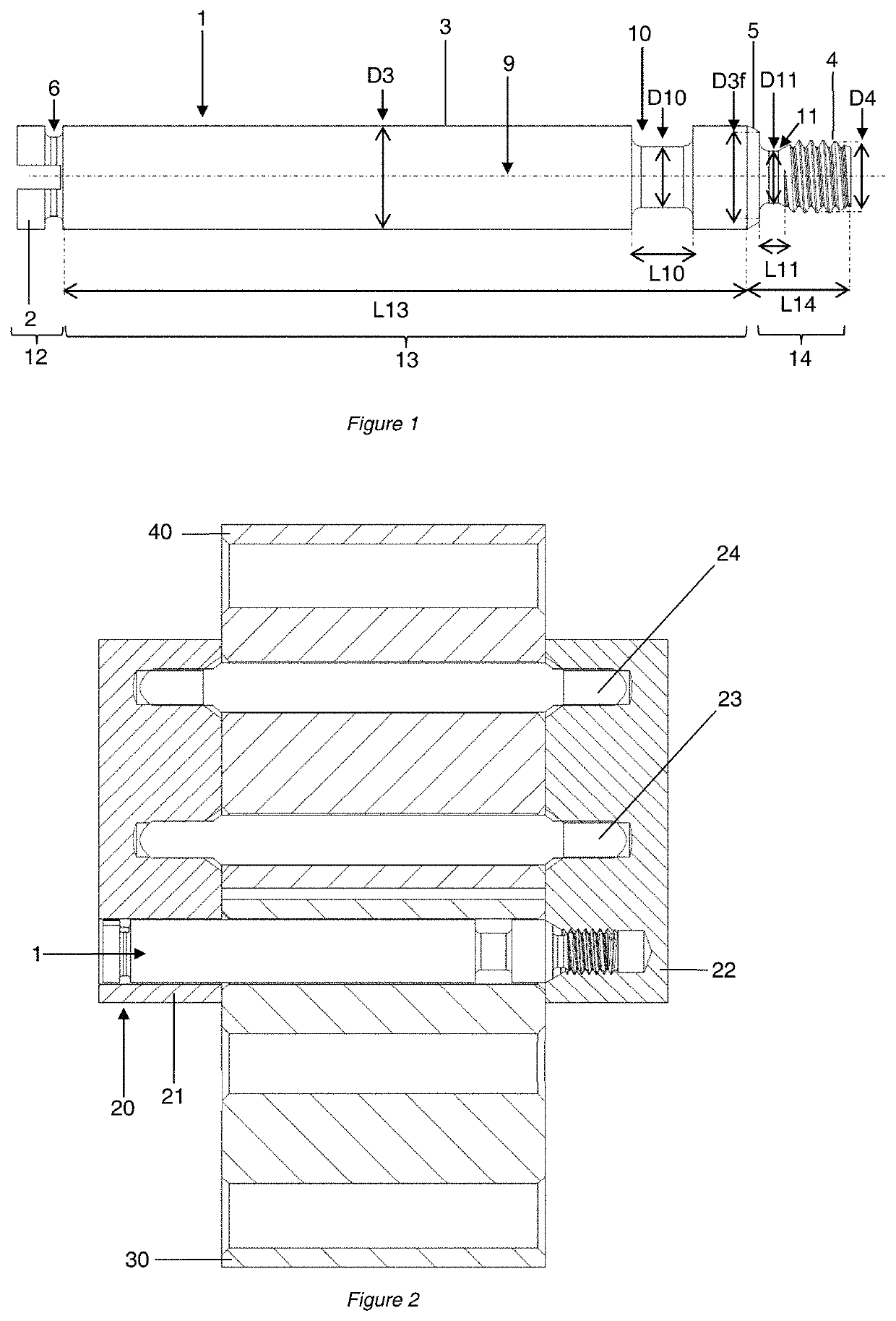
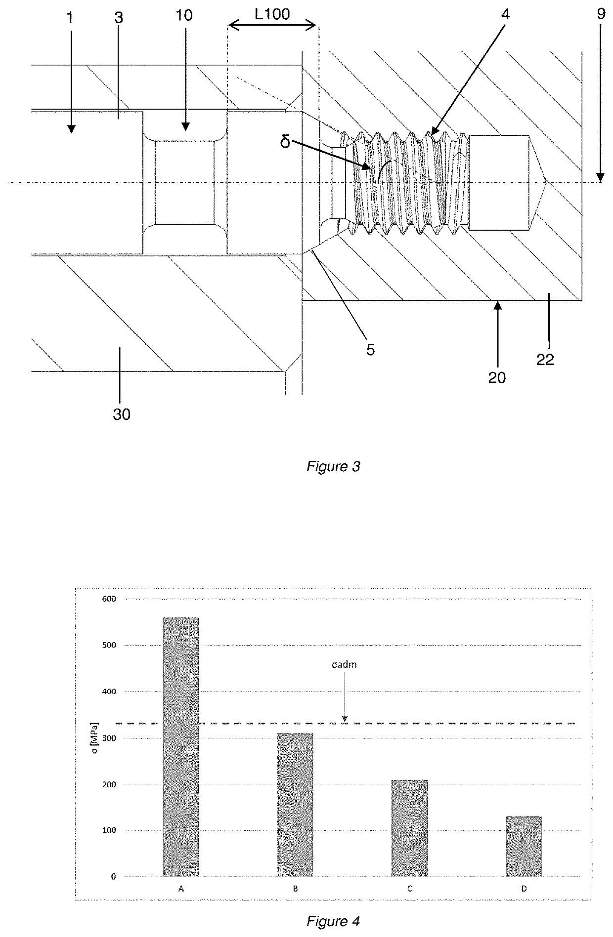
[0017]The invention relates to an assembly or articulation screw intended to assemble at least two horology components able to pivot relative to one another. It may notably be used for assembling links, for example links of a bracelet such as a wristwatch bracelet.

[0018]Thus, one embodiment will be described nonlimitingly hereinbelow in the context of the assembly of links of a watch bracelet. By convention, the direction parallel to the axis of the assembly screw will be referred to as the longitudinal direction and the perpendicular direction will be referred to as the transverse direction. In addition, the assembly screw will be considered in the direction in which it is introduced, its first end being opposite to its second end comprising its head, and the term upstream denoting a part oriented toward the side of this second end.

[0019]FIG. 1 depicts an assembly screw 1 according to one embodiment of the invention. This screw is arranged around a longitudinal axis 9, which forms ...


PUM


Abstract

Assembly screw (1) for the pivoting attachment of at least two horology components in a position of assembly, the assembly screw (1) comprising at least one guide portion (3) allowing one of the horology components to pivot, and at least one threaded portion (4) allowing it to be fixed to another horology component, wherein this screw comprises a shoulder (5) intended to come into abutment against this other horology component and a zone (10) of lower mechanical rigidity to reduce the contact pressure applied at the shoulder (5) of the assembly screw when the horology components are in the position of assembly.

Description

FIELD OF THE INVENTION[0001]This application claims priority of European patent application No. EP16174609.4 filed Jun. 15, 2016, the content of which is hereby incorporated by reference herein in its entirety.BACKGROUND ART[0002]The invention relates to an assembly or attachment screw for the pivoting assembly or attachment of at least two horology components, notably two links of a bracelet, for example a watch bracelet. It also relates to a bracelet and, more generally, to a timepiece, such as a wrist watch, both per se, comprising at least one such assembly screw for the pivoting assembly of at least two of their components.[0003]It is known practice to assemble two links of a watch bracelet using a pivoting-guidance pin supported by a screw, the assembled links being able to move rotationally relative to one another. An assembly of this type is exposed to a risk of unwanted unscrewing. This problem, well known to watchmakers, is caused by the repeated movements of the links rel...

Claims


Application Information

Patent Timeline
Patent Type & Authority Patents(United States)
IPC IPC(8): A44C5/02G04B13/02G04B31/00G04B37/14A44C5/10
CPCG04B31/00G04B13/02G04B37/1486A44C5/02A44C5/107A44C11/00F16B35/005F16B35/041F16B35/048F16C11/04
Inventor CATHELINE, ADRIENREJZNER, JAMES
Owner ROLEX SA
Why Eureka
Try Eureka