Rod insertion with adjustable rod angulation

a technology of angulation and rod insertion, which is applied in the field of rod insertion instruments with adjustable rod angulation, can solve the problems of altering the angular position of the rod, increasing the risk of injury to the patient, and thereby arising, and achieves the effects of convenient rod insertion, convenient assembly and disassembly, and simple operation

Active Publication Date: 2020-03-24
SILONY MEDICAL INT
View PDF49 Cites 0 Cited by
  • Summary
  • Abstract
  • Description
  • Claims
  • Application Information

AI Technical Summary

Benefits of technology

[0005]The object of the present invention is to provide a rod insertion instrument which, on the one hand, provides a simple and flexible adjustability of the fixation rod on the rod insertion instrument but, at the same time, enables a stable, secure but nevertheless easy-to-open fixing of the fixation rod.
[0006]A rod insertion device according to the invention for the insertion of a fixation rod into a pedicle screw comprises an in particular elongated receiving body, which has, at its distal end, a receiving recess with opposite side grooves, a clamping body arranged displaceably in the receiving body for clamping the transverse rod in the receiving recess of the rod insertion device, wherein, in an entry area, the in particular hook-shaped or curved side grooves of the receiving recess are formed in a first direction in the receiving body and, in a force-fitting area behind the entry area, are formed in a second direction different from the first direction, so that an inserted fixation rod is blocked in the first direction and / or wherein a blocking element is further provided in the receiving body, which, in particular along the entry direction of the receiving recess, is mounted movable between a release position and a blocking position and in particular is mounted displaceable in a translational manner. Both by means of the side groove with a change of direction and by means of the blocking element and, in particular, through the combination thereof, it can be ensured that the fixation rod can no longer fall out of the insertion position in the rod insertion device by accident. In particular, the side groove is at least partially formed as a through hole. The production of the side groove is thereby very simple, in particular if a second area is provided in a second direction.

Problems solved by technology

However, such a screw implies a certain effort for securing and especially for releasing the fixation rod after the operation and forces the user to bring his hands close to the inserted fixation rod for unscrewing the fastening.
An increased risk of injury to the patient can thereby also arise.
However, the operating lever for the push rod can be accidentally tightened further during the operation, which alters the angular position of the rod.

Method used


Image

  • Rod insertion with adjustable rod angulation
  • Rod insertion with adjustable rod angulation

Examples


Embodiment Construction

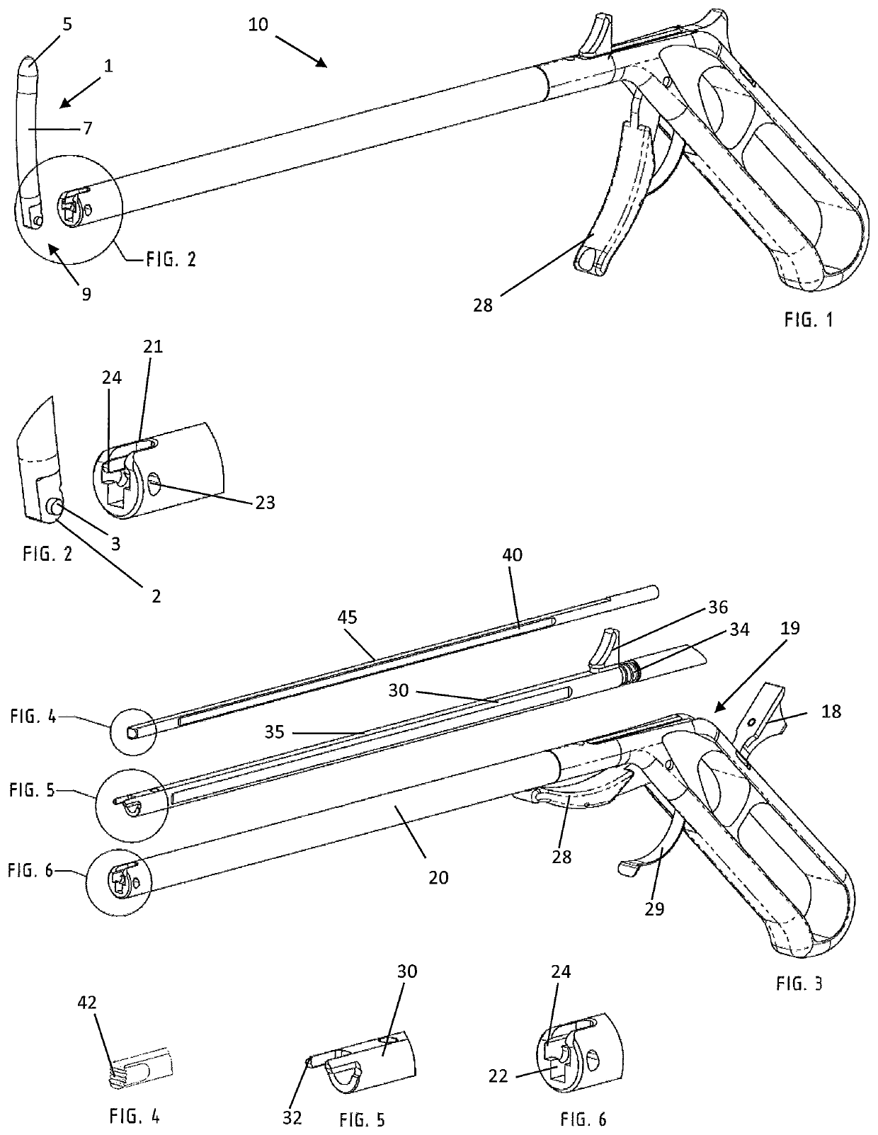
[0021]In the following, the terms axial, radial and circumferential as well as distal and proximal are used. Axial means a direction along the longitudinal axis of the instrument shown in FIG. 1, radial means a direction perpendicular to this longitudinal axis and circumferential means a direction around the longitudinal axis. Furthermore, the designations top, bottom, left and right are also used in relation to the instrument represented in FIG. 1. Distal refers to a side which points away from the user and proximal refers to the side directed towards the user.

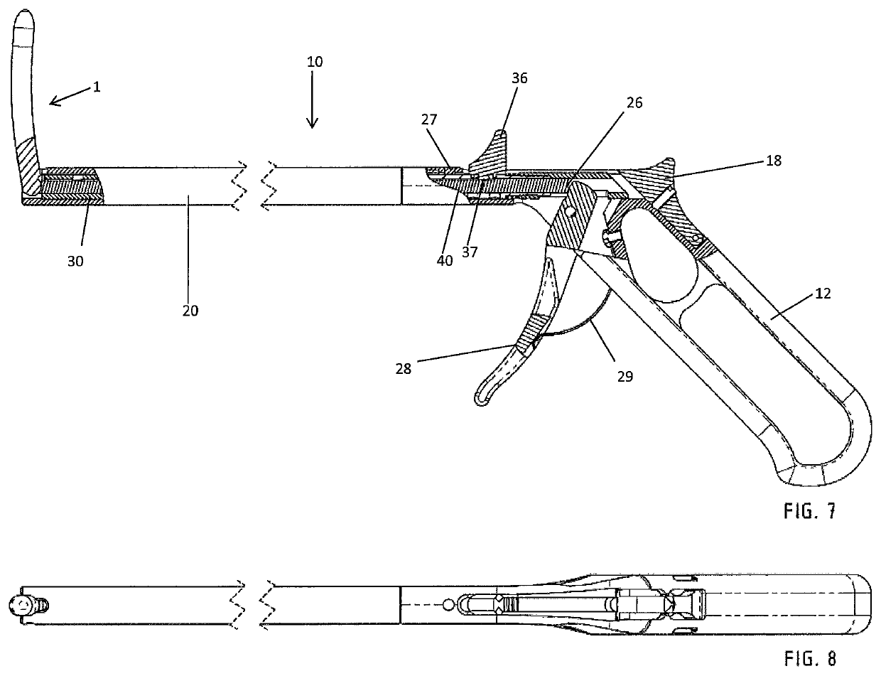
[0022]The preferred embodiment of the rod insertion device 10 is represented in FIG. 1. The rod insertion device essentially consists of an elongated main body, which is formed as a receiving body 20 and has, at a distal end, a receiving apparatus 22 for a fixation rod 1 and, at the other proximal end, a handle 12 for operating and guiding the instrument.

[0023]The fixation rod 1 can be seen in FIGS. 1, 7 and 8. There, it is f...


PUM


Abstract

The invention relates to a rod insertion device (10) for the insertion of a fixation rod (1) into a pedicle screw, comprising a receiving body (20), which has, at its distal end, a receiving recess (22) with opposite guide grooves (24), a clamping body arranged displaceably in the receiving body (20) for clamping the transverse rod in the receiving groove of the rod insertion device, wherein, in an entry area, the guide grooves of the receiving recess (22) are formed in a first direction in the receiving body (20) and, in a force-fitting area behind the entry area, are formed in a second direction different from the first direction, with the result that an inserted fixation rod is blocked in the first direction and / or in that a blocking element (30) is further provided with a detent (32), which is mounted movable between a release position and a blocking position.

Description

CROSS REFERENCE TO RELATED APPLICATIONS[0001]This application is a national application filed under 35 USC 371 of PCT Application PCT / EP2017 / 073272 filed 15 Sep. 2017 and claims priority from DE 10 2016 011 521.1 filed 23 Sep. 2016 both applications incorporated by reference in their entireties for all purposes.FIELD OF THE INVENTION[0002]The invention relates to a rod insertion instrument with adjustable rod angulation for the insertion of a fixation rod for pedicle screws.STATE OF THE ART[0003]In the state of the art, rod insertion instruments are usually used which hold the fixation rod at the end in a pre-determined position. Thus, the fixation rod is then pushed through two adjacent pedicle screws. In the state of the art, the fixation rods are fixed, for example, by screw mechanisms. Thus, in DE 10 2013 107 308 A1, a rod insertion instrument for the insertion of a fixation rod into the tulips of adjacent pedicle screws is described, which discloses a grip portion, a tube secti...

Claims


Application Information

Patent Timeline
Patent Type & Authority Patents(United States)
IPC IPC(8): A61B17/70
CPCA61B17/7083A61B17/7085A61B17/7089A61B17/7011
Inventor RIESINGER, RALF
Owner SILONY MEDICAL INT
Why Eureka
Try Eureka