Chirp pulse stretcher

A technology of chirped pulse and stretcher, which is applied in the field of chirped pulse stretcher, which can solve problems such as escape, inability to achieve adjustment, and loss of pulse energy

Inactive Publication Date: 2007-02-07
SHANGHAI INST OF OPTICS & FINE MECHANICS CHINESE ACAD OF SCI
View PDF4 Cites 0 Cited by
  • Summary
  • Abstract
  • Description
  • Claims
  • Application Information

AI Technical Summary

Problems solved by technology

[0005] 1. When these pulse stretchers are used together with a grating-to-pulse compressor to form a stretching and compression system, they cannot completely compensate the third-order and fourth-order dispersions imposed by the laser amplification medium and other optical components on the chirped pulse. There will still be residual uncompensated third- and fourth-order dispersion in the subsequent pulse
In this way, the intensity contrast of the pulse after stretching, amplifying and compressing is low, generally in the range of 10 2 ~10 5 between, which seriously affects the experimental results, and limits the intensity contrast ratio of ultrashort pulses to be greater than 10 6 The use of plasma experiments in
[0006] 2. Because the dispersion of each order imposed by the pulse stretcher on the pulse affects each other, that is to say, while adjusting the second-order dispersion imposed by the stretcher on the pulse, it also changes the third-order and fourth-order dispersions; when changing the stretcher When third-order dispersion is applied to the pulse, it also affects higher-order dispersion such as second and fourth orders
In this way, it is impossible to independently adjust the dispersion of each order without affecting other dispersions, so as to achieve complete compensation of the third and fourth order dispersions
[0007] 3. Since the pulse only undergoes compensation once in the stretcher, as well as the limited size of the grating and other optical components, only part of the wavelength components can be completely captured by the stretcher, and the large dispersion of the grating causes part of the wavelength components to escape from the stretcher, which means The loss of pulse energy and the incompleteness of the spectrum will make the final pulse broaden to a certain extent (~15%)

Method used


Image

  • Chirp pulse stretcher
  • Chirp pulse stretcher
  • Chirp pulse stretcher

Examples


Embodiment Construction

[0030] The present invention will be further described below in conjunction with specific embodiments and accompanying drawings, but the protection scope of the present invention should not be limited thereby.

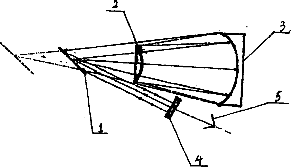
[0031] see first Figure 5 , Figure 5 It is a structural schematic diagram of an embodiment of the pulse stretcher of the present invention. It can be seen from the figure that the ultrashort pulse stretcher of the present invention includes a total reflection pulse stretcher 1, a dispersion fine tuner 2, a total reflection mirror 3, a translation coarse adjustment three-dimensional stage 4 and two Dimensional manual translation stage 5, described total reflection pulse stretcher 1 is made up of spherical concave reflector 11, grating 12 and plane reflector 13 successively, and the rotation axes of described spherical concave reflector 11 and plane reflector 13 are at the same On a straight line, wherein the plane reflector 13 is placed on the focal plane of the sphe...


PUM

PropertyMeasurementUnit
radiusaaaaaaaaaa
thicknessaaaaaaaaaa

Abstract

Disclosed stretcher includes a total reflection pulse stretcher, a fine adjuster for color dispersion, a 2D manual shift platform, and 3D shift coarse adjustment platform. The total reflection pulse stretcher is composed of spherical concave mirror, grating and plane reflector, and the fine adjuster for color dispersion is composed of a plano concave lens, a biconvex lens and a biconcave lens. The plane reflector is positioned at focal plane of spherical concave mirror. The grating is in confocal cavity. Composite lens of plano concave and biconvex lens is in virtual confocal to biconcave lens. A plane reflector is setup at output end of the fine adjuster. The invention realizes full compensation in third and fourth order dispersion, obtains highquality laser pulse amplified, raises contrast of intensity and focusing intensity, and doubled stretching factor.

Description

technical field [0001] The present invention is related to chirped pulses, in particular to a chirped pulse stretcher used in ultrashort ultrahigh-power laser systems, which is mainly suitable for improving the beam quality of ultrashort pulses and further improving ultrashort (10 -15 ~10 -12 seconds) Super (10 12 ~10 15 Watts) output power and output energy of the laser. technical background [0002] In an ultra-short and ultra-intense laser system, when the laser intensity reaches GW / cm 2 , the nonlinear refractive index of the laser medium will play a significant role. Nonlinearity leads to full-beam aperture self-focusing and small-aperture self-focusing in the laser system, and eventually destroys the laser medium, thus hindering the further increase of laser peak power. Therefore, the generation of ultra-short and ultra-intense laser must effectively extract energy from the laser amplifying medium to obtain high-efficiency amplification. At the same time, it must ...

Claims


Application Information

Patent Timeline
Patent Type & Authority Patents(China)
IPC IPC(8): H01S3/00G02B27/44G02F1/35
Inventor 杨鑫谢兴龙李美荣薛志玲高奇
Owner SHANGHAI INST OF OPTICS & FINE MECHANICS CHINESE ACAD OF SCI
Why Eureka
Try Eureka