Guide device

a technology of guide wire and distal end, which is applied in the direction of tyres, domestic applications, other domestic articles, etc., can solve the problems that the clamping device may not clamp the distal end of the steel wire in the appropriate manner, and achieve the effect of limiting the twisting of the steel wir

Active Publication Date: 2020-03-31
THE YOKOHAMA RUBBER CO LTD
View PDF17 Cites 1 Cited by
  • Summary
  • Abstract
  • Description
  • Claims
  • Application Information

AI Technical Summary

Benefits of technology

[0012]The guide device succeeds in limiting twisting of the steel wire in the guideway.

Problems solved by technology

Thus, the clamping device may fail to appropriately clamp the distal end of the steel wire.

Method used


Image

  • Guide device
  • Guide device
  • Guide device

Examples


Embodiment Construction

[0028]A bead core formation apparatus 1 according to one embodiment will now be described.

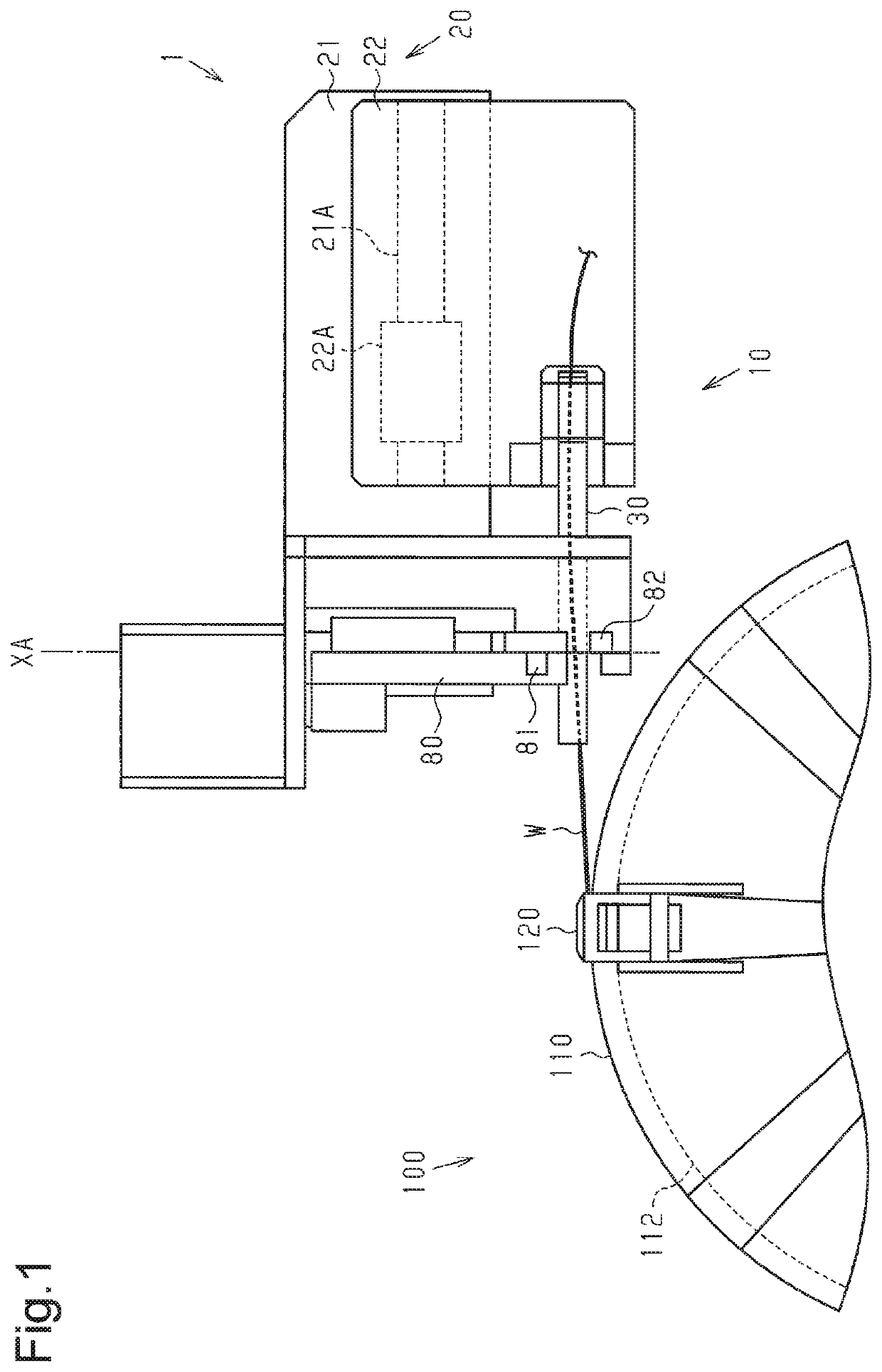
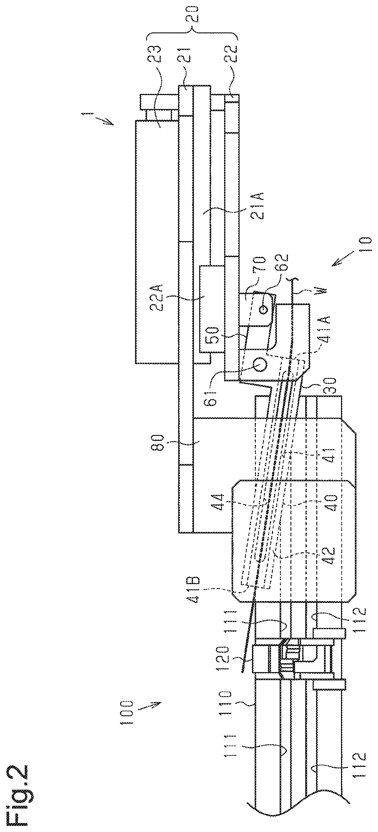
[0029]As shown in FIG. 1, the bead core formation apparatus 1 includes a guide device 10, through which a rubber-coated steel wire W passes, a cutting device 80, which cuts the steel wire W, and a winding device 100, which forms a bead core by winding the steel wire W that is fed by the guide device 10. The steel wire W is bent in conformance with the diameter of a bead prior to being fed to the guide device 10 by a feeding roller (not shown).

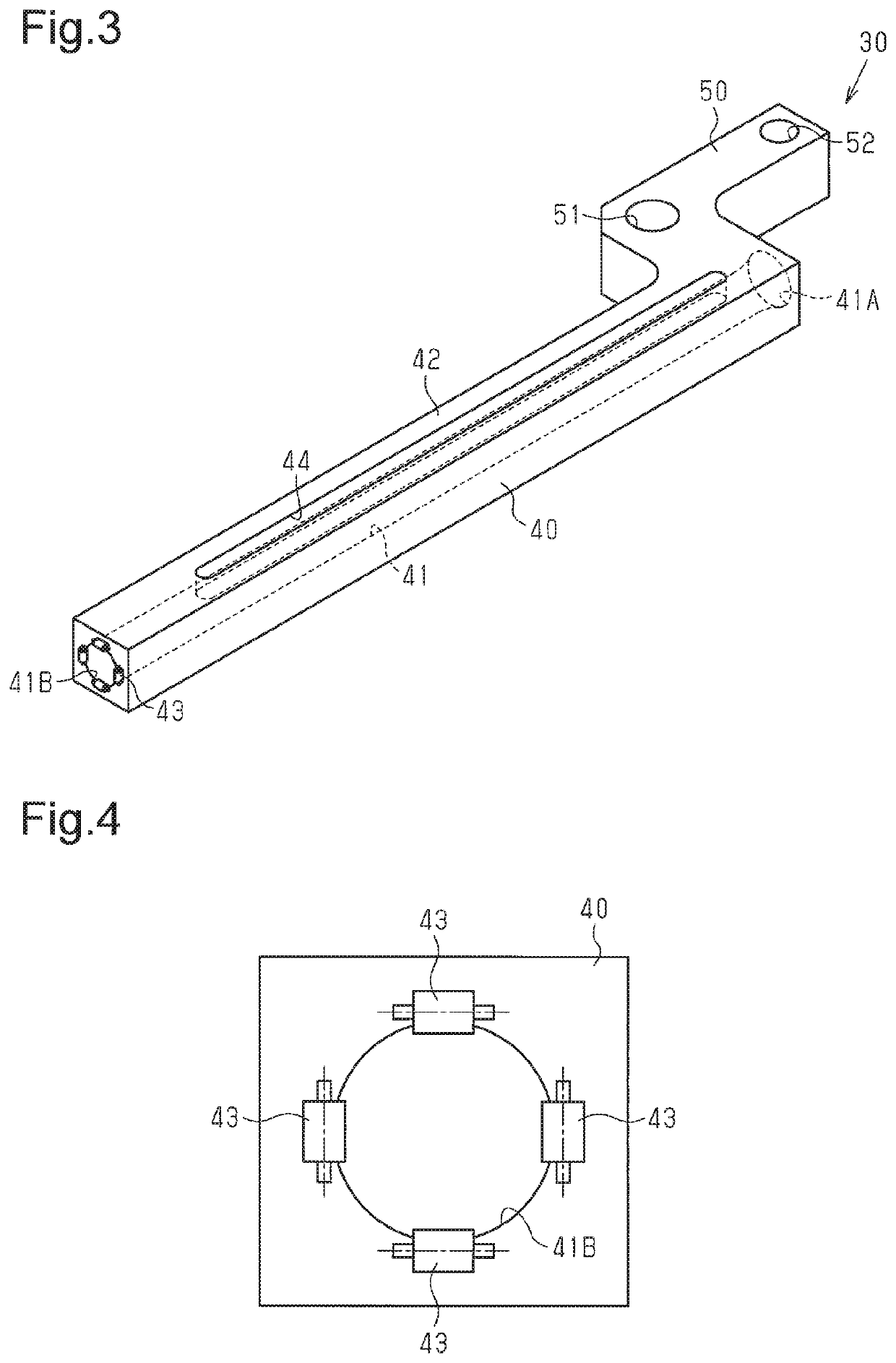
[0030]The guide device 10 includes a device body 20 and a steel wire passing portion 30, through which the fed steel wire W passes.

[0031]As shown in FIG. 2, the device body 20 includes a first support plate 21, to which the cutting device 80 is coupled, a second support plate 22, to which the steel wire passing portion 30 is coupled, and an actuator 23, which moves the second support plate 22 relative to the first support plate 21. The second support plate...


PUM

PropertyMeasurementUnit
diameteraaaaaaaaaa
resistanceaaaaaaaaaa
shapesaaaaaaaaaa

Abstract

A guide device includes a guideway through which a steel wire passes when the steel wire is fed to a former. The guideway includes an inner surface. At least a portion of the inner surface includes a slit or recess at a position corresponding to a direction in which the steel wire is bent.

Description

RELATED APPLICATIONS[0001]The present invention is a U.S. National Stage under 35 USC 371 patent application, claiming priority to Serial No. PCT / JP2014 / 072426, filed on 27 Aug. 2014; the entirety of which is incorporated herein by reference.TECHNICAL FIELD[0002]The present invention relates to a guide device that includes a guideway through which a steel wire passes when the steel wire is fed to a former.BACKGROUND ART[0003]A guide device known in the art includes a guideway through which a steel wire passes when the steel wire is fed to a former to form a bead core, which is embedded in a bead of a tire.[0004]Patent document 1 describes an example of a guide device that is located between a feeding roller, which feeds a rubber-coated steel wire, and a former, around which the steel wire is wound. The guide device includes a tetragonal housing and a guideway, which is located in the housing. The steel wire, which is fed by the feeding roller, passes through the guideway. The feedin...

Claims


Application Information

Patent Timeline
Patent Type & Authority Patents(United States)
IPC IPC(8): B29D30/48
CPCB29D30/48B29D2030/485B29D2030/487B29D2030/488B29D2030/0044B21F3/00
Inventor TAKAGI, CHIKARA
Owner THE YOKOHAMA RUBBER CO LTD
Why Eureka
Try Eureka