Device and method for block compression and block decompression

a block compression and decompression technology, applied in the field of block compression, can solve problems such as the cause of image quality deterioration, and achieve the effect of suppressing image quality deterioration

Active Publication Date: 2020-03-31
SYNAPTICS JAPAN GK
View PDF10 Cites 0 Cited by
  • Summary
  • Abstract
  • Description
  • Claims
  • Application Information

AI Technical Summary

Benefits of technology

[0007]Therefore, an objective of the present disclosure is to provide a technique for suppressing image quality deterioration caused by block compression. Other objectives and new features of the present disclosure would be understood by a person skilled in the art from the following disclosure.

Problems solved by technology

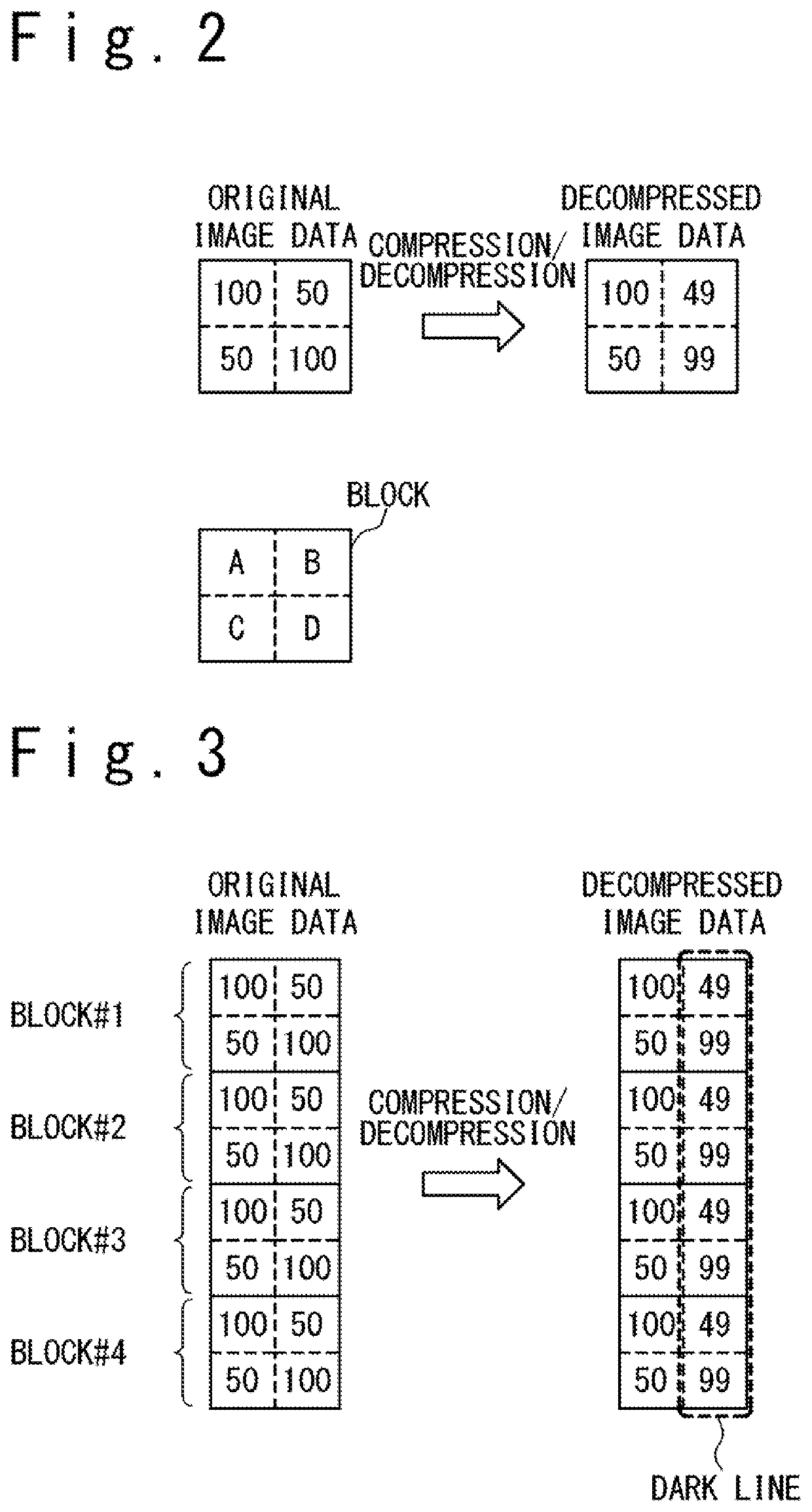
As a result of inventors' study with respect to image deterioration in block compression including a quantization process, the inventors have discovered that a sort of image quality deterioration is caused by inappropriate generation of dither values used in the quantization process.

Method used


Image

  • Device and method for block compression and block decompression
  • Device and method for block compression and block decompression
  • Device and method for block compression and block decompression

Examples


implementation example

[0128](Implementation Example)

[0129]In the following, a description is given of a further specific implementation example of the image compression and decompression system configured to select a compression process used for block compression of the image data of each block in response to the feature of the image data of each block.

[0130]FIG. 12 is a block diagram illustrating the configuration of a block compression circuitry 71 of the image compression and decompression system in the present implementation example. The block compression circuitry 71 is configured to generate compressed image data DCMP by performing block compression on image data DIMG of the RGB format. The block compression circuitry 71 illustrated in FIG. 12 may be used as the block compression circuitry 62 integrated in the display driver 52 of the display device 50 illustrated in FIG. 10 or the block compression circuitry 54 integrated in processor 53A of the display device 50A illustrated in FIG. 11.

[0131]Also...

case b

[0148]In the block decompression processing of the present example, the pixel correlation determination circuit 86 of the block compression circuitry 71 determines which of the cases described below the correlation among the image data of the four pixels of the compression target block falls into:[0149]Case A: image data of any two pixels selected from the four pixels are poorly correlated for any possible combinations of the two pixels (see FIG. 14A).[0150] image data of two pixels are highly correlated and image data of the remaining two pixels are poorly correlated with each other and also poorly correlated with those of the preceding two pixels (see FIG. 14B).[0151]Case C: image data of two pixels are highly correlated and image data of the remaining two pixels are also highly correlated (see FIG. 14C).[0152]Case D: image data of the four pixels are highly correlated (FIG. 14D).

[0153]FIG. 15 is a flowchart illustrating an exemplary procedure for determining the correlation in th...


PUM


Abstract

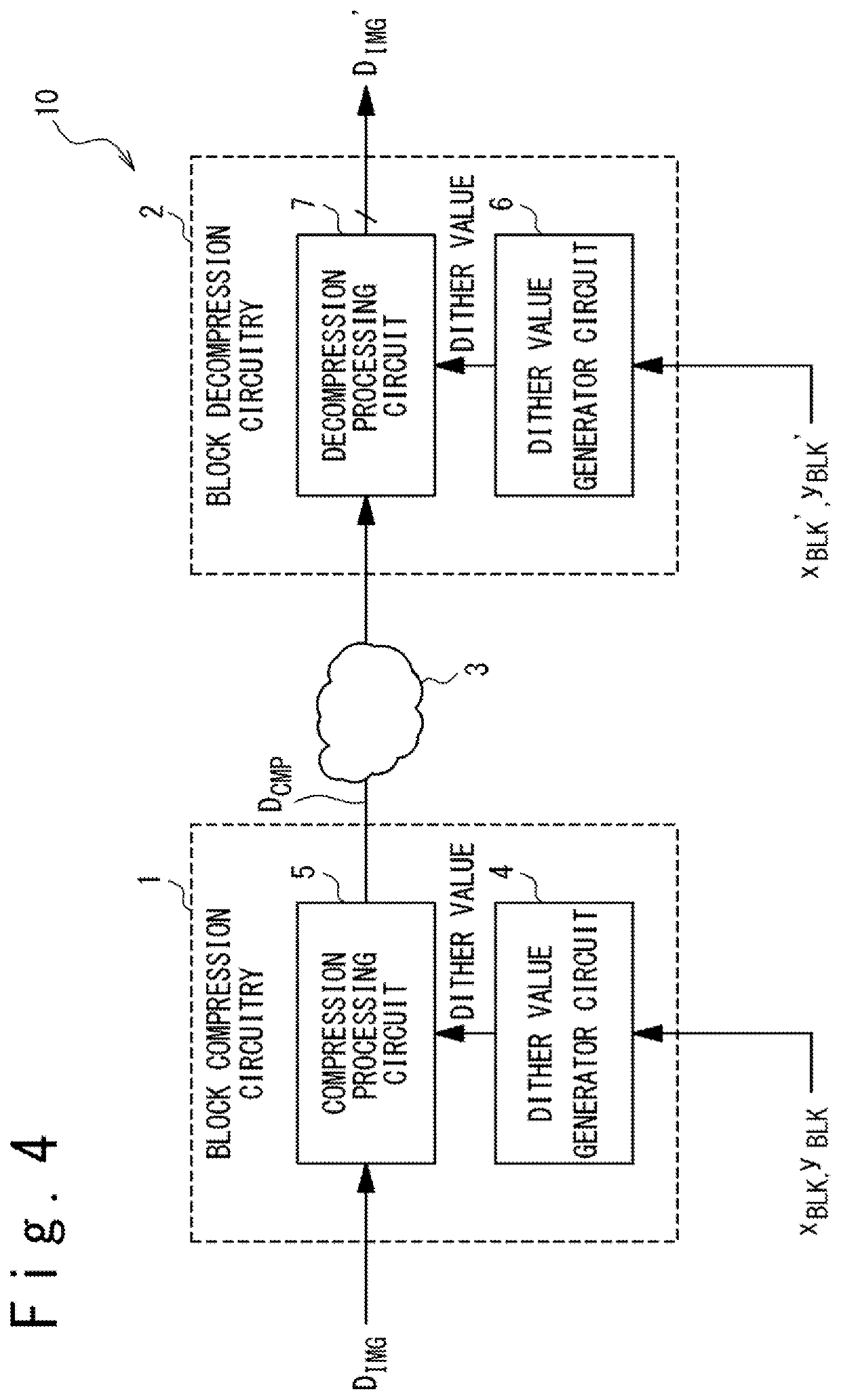
An image compression device includes: a first compression processing circuit configured to generate a first compressed image data by performing a first block compression process on an image data and a dither value generator circuit. When the first compressed image data associated with a compression target block is generated, the dither value generator circuit is configured to generate at least one dither value in response to block coordinates indicating a position of the compression target block in an image and the first compression processing circuit is configured to perform a quantization process using the at least one dither value in the first block compression process.

Description

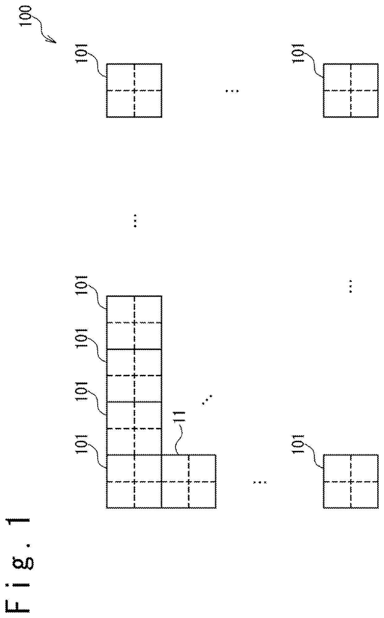
CROSS REFERENCE[0001]This application claims priority of Japanese Patent Application No. 2016-096958, filed on May 13, 2016, the disclosure of which is incorporated herein by reference.TECHNICAL FIELD[0002]The present invention relates to an image compression device, image decompression device, image compression and decompression system and a display driver, more particularly, to block compression in which image data are compressed in units of blocks.BACKGROUND ART[0003]Block compression, in which image data are compressed in units of blocks, is one of the most widely used techniques for compressing image data. A block referred herein is a unit of compression processing defined by dividing a frame image; a block is composed of a predetermined number of pixels arranged in a specific arrangement (for example, arrayed in n rows and m columns for n and m being integers at least one of which is two or more).[0004]FIG. 1 schematically illustrates one example of definition of blocks. A fra...

Claims


Application Information

Patent Timeline
Patent Type & Authority Patents(United States)
IPC IPC(8): H04N19/426H04N19/124H04N19/176
CPCH04N19/176H04N19/426H04N19/124H04N19/86G06T9/00G09G5/00G09G2340/02H04N19/136H04N19/182H04N19/119
Inventor FURIHATA, HIROBUMIORIO, MASAO
Owner SYNAPTICS JAPAN GK
Why Eureka
Try Eureka