Image signal processing device

a signal processing and image technology, applied in the direction of electric digital data processing, instruments, computing, etc., can solve the problem of image quality degradation of images displayed on the screen of liquid crystal display devices, and achieve the effect of suppressing image quality degradation

Active Publication Date: 2012-10-16
THINE ELECTRONICS
View PDF11 Cites 0 Cited by
  • Summary
  • Abstract
  • Description
  • Claims
  • Application Information

AI Technical Summary

Benefits of technology

[0010]The present invention has been developed in order to solve the above-mentioned problems and an object thereof is to provide an image signal processing device that employs the overdrive technique in which corrected image data is acquired by a lookup table and interpolation calculation and capable of suppressing image quality from deteriorating due to a flicker etc.
[0019]With the image signal processing device according to the present invention, it is possible to suppress image quality from deteriorating due to a flicker etc. by employing the overdrive technique to acquire corrected image data using a lookup table or by interpolation calculation.

Problems solved by technology

However, with the overdrive technique in which the corrected image data G2′ is acquired from the lookup table and by interpolation calculation as described above, if the corrected image data G2′ acquired by interpolation calculation is given to a liquid crystal display device, there may be a case where the image quality of an image displayed on a screen of the liquid crystal display device is deteriorated due to a flicker etc.

Method used


Image

  • Image signal processing device
  • Image signal processing device
  • Image signal processing device

Examples


Embodiment Construction

[0036]Preferred embodiments to embody the present invention are described below in detail with reference to the accompanied drawings. In the description of the drawings, the same symbols are attached to the same components and duplicated description is omitted.

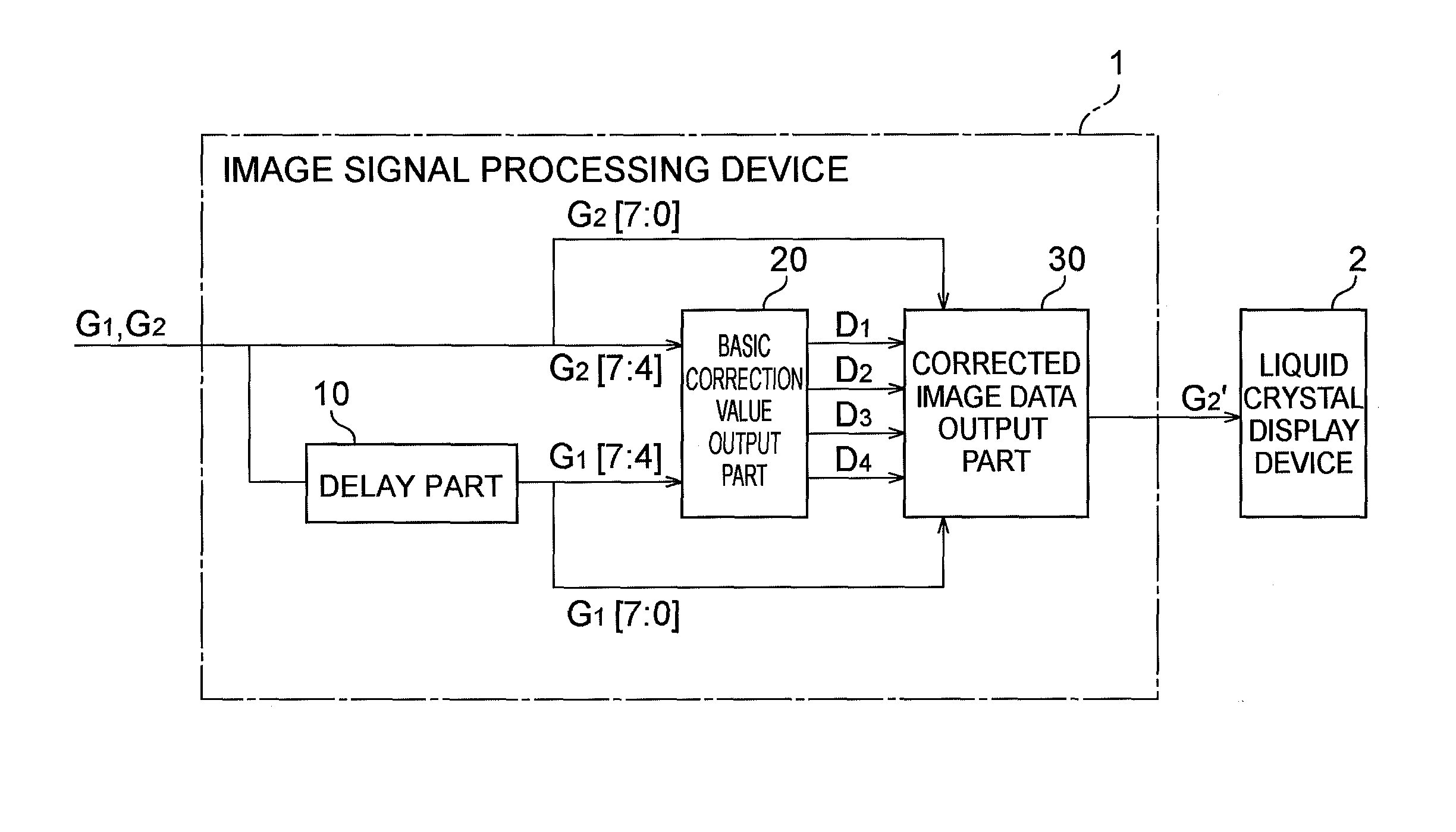
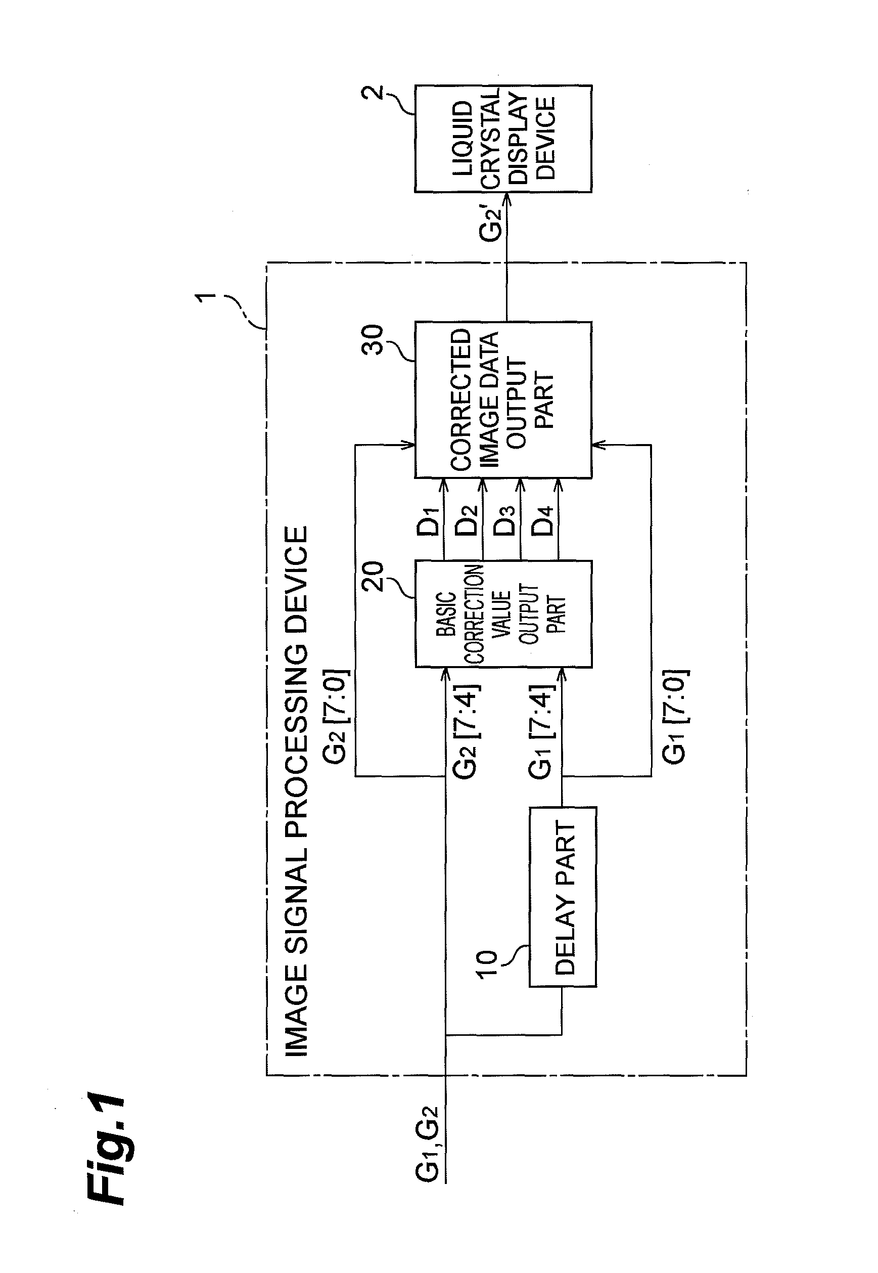
[0037]FIG. 1 is a diagram showing a configuration of an image signal processing device 1 according to the present embodiment. The image signal processing device 1 outputs an image signal to a liquid crystal display device 2 after processing image data of each frame of the image signal, and comprises a delay part 10, a basic correction value output part 20 and a corrected image data output part 30. Hereinafter, it is assumed that the image data (luminance) is 8-bit data. In the case of a color image, each image data of each color is assumed to be 8-bit data and the image data of one color of the color image is described below, however, the description applies also to the image data of the other colors.

[0038]To the delay part 10...


PUM


Abstract

An image signal processing device 1 comprises a delay part 10, a basic correction value output part 20, and a corrected image data output part 30. To the basic correction value output part 20, data G1[7:4] of high order 4 bits of image data G1[7:0] of a first frame to be output from the delay part 10 is input and data G2[7:4] of high order 4 bits of image data G2[7:0] of a second frame to be input to the delay part 10 is input, and the basic correction value output part 20 outputs basic correction values D1 to D4 corresponding to the data. To the corrected image data output part 30, G1[7:0], G2[7:0] and D1 to D4 are input, and the corrected image data output part 30 performs when “G1[7:4]=G2[7:4]” holds and performs different processing when “G1[7:4]≠G2[7:4]” holds, and acquires corrected image data G2′[7:0] corresponding to data (G1[7:0], G2[7:0]) by interpolation calculation.

Description

TECHNICAL FIELD[0001]The present invention relates to an image signal processing device that outputs an image signal to a liquid crystal display device after processing image data of each frame of the image signal.BACKGROUND ART[0002]An image display device is roughly classified into an impulse type display device and a hold type display device. In a CRT (Cathode Ray Tube) mentioned of as an example of an impulse type display device, a screen is scanned by an electron gun and a display is produced only in pixels that electron beams have reached. In contrast to this, in a liquid crystal display device or an organic electroluminescence display device mentioned of as a hold type display device, a frame of an image signal is updated at a fixed period and when a display of an image of a certain first frame is specified, the display of the image of the first frame is held until a display of an image of a second frame that follows is specified. Compared to an impulse type display device, a...

Claims


Application Information

Patent Timeline
Patent Type & Authority Patents(United States)
IPC IPC(8): G09G5/10
CPCG09G3/3611G09G2320/0252G09G2340/16
Inventor HIGUCHI, TOMOHISA
Owner THINE ELECTRONICS
Why Eureka
Try Eureka