Vacuum splint apparatus for accessing the neck of a patient and method for using the same

a technology of splints and neck braces, which is applied in the direction of machines/engines, liquid fuel engines, positive displacement liquid engines, etc., can solve the problems of many adjustments, and the neck brace inflatable could be more detrimental to the treatment of patients than other braces, so as to prevent the restriction of venous blood flow and prevent the distraction of the neck of a patien

Active Publication Date: 2020-04-07
ISLAVA STEVE
View PDF9 Cites 2 Cited by
  • Summary
  • Abstract
  • Description
  • Claims
  • Application Information

AI Technical Summary

Benefits of technology

[0016]In one particular embodiment, removing air from the internal volume of the neck brace through the vacuum line also involves preventing the plurality of compressible particles within the internal volume from escaping and entering the vacuum line by means of a filter screen.
[0019]In a related embodiment, the step of forming a unique rigid mold about the neck and chin of the patient further includes preventing restriction of the venous blood flow return of the patient.
[0020]Finally, the current invention provides a method for preventing the distraction of the neck of a patient when immobilizing the patient's neck. Here, the method includes disposing a neck brace about the neck of a patient while the neck of the patient is in an injured position. Next, the neck brace is actuated to form a unique rigid mold about the injured region of the patient's neck, the formed unique rigid mold being configured to maintain the neck of the patient within its original injured position for the duration that the neck brace is disposed about the neck of the patient. Access to the neck of the patient after the neck brace has been actuated is further provided by an access port defined within the neck brace itself.

Problems solved by technology

A problem with many neck braces, however, is that many of them must be adjusted before being applied to the patient's neck.
Again, in emergency situations when time and physical access to the injured patient may be limited, such an inflatable neck brace could prove to be more detrimental to the treatment of the patient than other braces.

Method used


Image

  • Vacuum splint apparatus for accessing the neck of a patient and method for using the same
  • Vacuum splint apparatus for accessing the neck of a patient and method for using the same
  • Vacuum splint apparatus for accessing the neck of a patient and method for using the same

Examples


Embodiment Construction

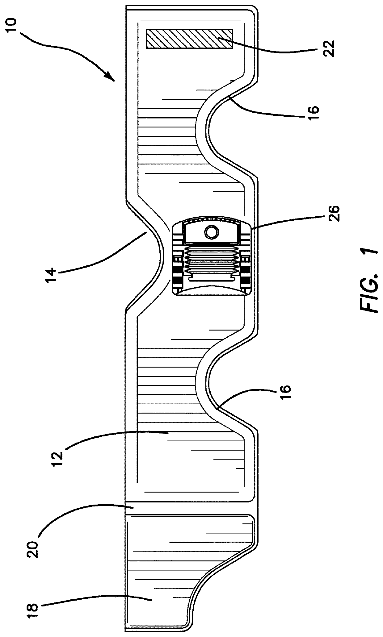
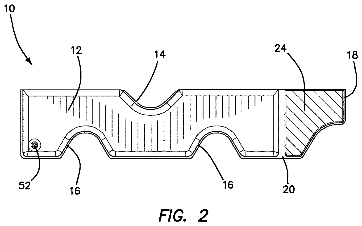
[0048]Greater detail of the illustrated embodiments of the current invention may be had by turning to FIGS. 1 and 2 which shows the current neck brace denoted generally by reference numeral 10. FIG. 1 shows a frontal view of the brace 10 which comprises of a body 12 that is substantially rectangular in shape. The body 12 itself comprises a neck cutout 14 and a plurality of shoulder cutouts 16. The neck cutout 14 and shoulder cutouts 16 are sized and defined in the body 12 at the appropriate locations so that when the neck brace 10 is applied to a patient's neck region, the neck cutout 14 appropriately accommodates the jaw and head of the patient while the shoulder cutouts 16 accommodate the shoulders and chest region of the patient as is known in the art. The body 12 itself is comprised of soft vinyl or other flexible material and is filled with a plurality of foam micro beads known in the art.

[0049]The body 12 further comprises a coupling portion 18 joined to the remainder of the b...


PUM


Abstract

A particle filled neck brace used for immobilizing the neck and chin of a patient which includes a vacuum pump disposed on the neck brace, which pump is communicated to the interior of the neck brace. After the neck brace is secured around the neck and chin of the patient, the vacuum pump is manipulated to remove air from the neck brace to form a rigid mold about the patient's neck and chin. The vacuum pump has a one way directional valve so that the neck brace remains in a rigid configuration for as long as the neck brace is applied to the patient. The neck brace also forms a rigid mold over the patient's chin so as to immobilize the patient as well as to provide a comfortable fit without inducing further distracting the patient or restricting the patient's venous return blood flow.

Description

RELATED APPLICATIONS[0001]The present application is a Continuation in Part application of U.S. application Ser. No. 15 / 496,881, filed on Apr. 25, 2017, which is a Continuation in Part application of U.S. application Ser. No. 15 / 061,820, filed on Mar. 4, 2016, which in turn is a Continuation in Part application of U.S. application Ser. No. 14 / 962,862, filed on Dec. 8, 2015, which are incorporated herein by reference and to which priority is claimed pursuant to 35 USC 120.BACKGROUNDField of the Technology[0002]The invention relates to the field of pneumatic splints, specifically a vacuum operated splint for immobilizing the neck of a patient.Description of the Prior Art[0003]Medical splints and other immobilizers have long been used to immobilize or otherwise restrict the physical movement of a region or limb of an injured patient. Many traditional splints are made from cardboard, plastic, padded board, or fiberglass and may either be generic in shape or specifically formed to fit a ...

Claims


Application Information

Patent Timeline
Patent Type & Authority Patents(United States)
IPC IPC(8): A61F5/058F04B53/10A61F5/055F04B45/02F04B33/00
CPCF04B33/00A61F5/05883F04B53/10F04B45/02A61F5/055A61F5/05833
Inventor ISLAVA, STEVE
Owner ISLAVA STEVE
Why Eureka
Try Eureka