Lighting device on grid sheet carrier

a technology of grid sheet and light, which is applied in the direction of lighting, lighting and heating apparatus, light source combinations, etc., can solve the problems of undesired spottiness and/or inhomogeneous illumination, the overall efficiency of the known grid sheet lighting device is relatively low, and the suitable use of the known lighting device is limited to a relatively small number of applications. , to achieve the effect of improving the homogeneity of observed illumination area, increasing the opening size, and improving the uniform

Active Publication Date: 2020-04-07
SIGNIFY HLDG BV
View PDF19 Cites 0 Cited by
  • Summary
  • Abstract
  • Description
  • Claims
  • Application Information

AI Technical Summary

Benefits of technology

[0012]The inventive lighting device enables very minimalistic designs. Quite often when an elegant design was made using high-power LEDs the technical requirement of a large heatsink, to keep the LEDs at an acceptable temperature, ruined the appearance of the design. In the inventive lighting device, the large surface covered with low- or mid-power LEDs is quite well capable of keeping the LEDs cool, and the grid is ultra-thin as it is basically just a grid of sheet metal. So, this enables the designer to apply minimalism in every way. The transparency of the grid sheet carrier enables to see the structure behind the grid sheet carrier, so in the off state the grid sheet carrier blends in with the environment, while in the on state, the structure behind the grid sheet carrier can be used as a projection canvas. Because the LEDs are packed closely together on a relative small area, creation of a dynamic light content with a very high perceived dynamic resolution is enabled and at the same time provide a very cost effective solution.
[0030]The lighting device can have the first pattern made in modules, but preferably is made in one integral part to form one integral body, for example via a relatively and easy stamp and die process. This involves a well-known and simple manufacturing process step thus rendering the lighting device to be relatively cheap.

Problems solved by technology

This, however, involves the risk of undesired spottiness and / or inhomogeneous illumination.
This, however, involves the disadvantages that the overall efficiency of the known grid shaped lighting device is relatively low and its obtrusive appearance / presence in the off-state when it has little or no aesthetical value, basically a white box on the wall.
This, however, involves the disadvantage that the suitable use of the known lighting device is limited to only a relatively small number of applications.

Method used


Image

  • Lighting device on grid sheet carrier
  • Lighting device on grid sheet carrier
  • Lighting device on grid sheet carrier

Examples


first embodiment

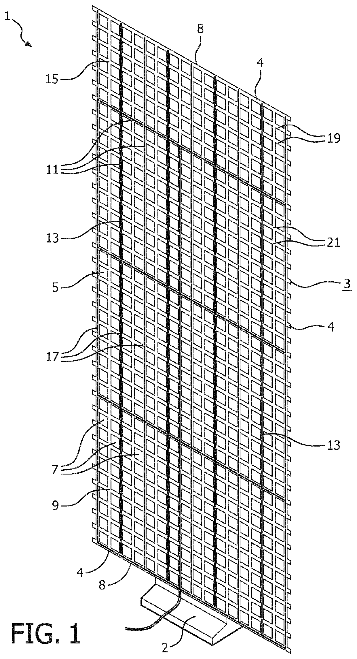
[0039]FIG. 1 shows a prototype of the lighting device 1 according to the invention illustrating the principle structure of the lighting device. The lighting device comprises a grid sheet carrier 3 having a border 4 having two opposite side edges 8. The grid sheet carrier comprising an open surface area 5 which is the sum of a plurality of openings 7 and comprising carrier material 9 surrounding each of said openings with a respective perimeter 10 of grid sheet carrier material, said carrier material being arranged in a two-dimensional, first pattern 11 which is similar to the shape of a trellis. The grid sheet carrier is mounted via a part of its side edges 8 of border 4 on a base part 2. A plurality of LEDs 13 mounted on both bridges 19 and nodes 21 on only a first main face 15 of the carrier material and arranged in a two-dimensional, second pattern 17 of parallel lines. The LEDs arranged to aim light toward a reflective surface during operation such that a majority of said light ...

second embodiment

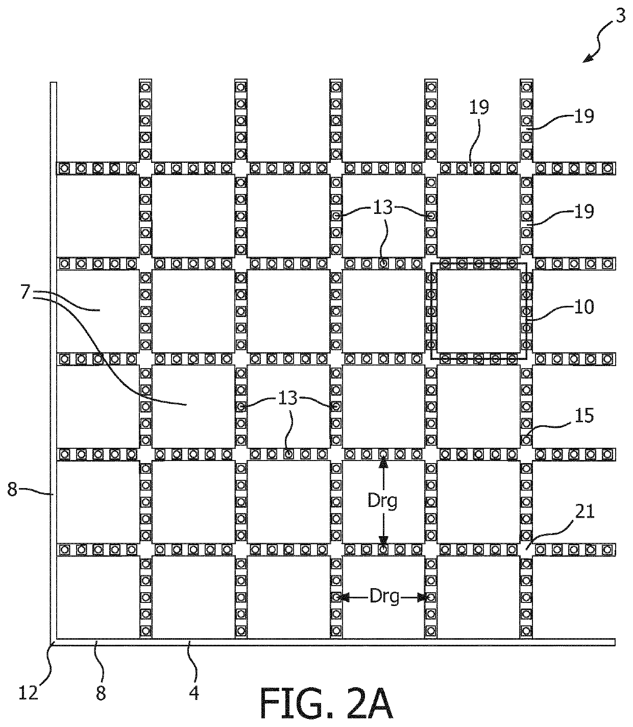
[0040]FIG. 2A shows a portion of a grid sheet carrier 3 according to the invention to be mounted via a corner 12 formed by side edges 8 of its border 4 on a base part (not shown) with FIG. 2B showing a detail of said grid sheet. The grid sheet carrier comprises a plurality of square shaped openings 7 and a plurality of LEDs 13 mounted on one, i.e. the first, main face 15 of the grid sheet carrier. The LEDs are mounted as a row of five LEDs on each side of the perimeter 10 of each opening, i.e. only at bridges 19 between the openings and not at nodes 21. Hence, the number of associated LEDs per opening is twenty and the ratio R between the number of LEDs and openings is ten, as each row of five LEDs is shared between two adjacent openings. The shortest distance between LEDs of opposite sides is the same as the average distance Drg between LEDs on opposite sides around one opening.

[0041]In this embodiment the LEDs are individually addressable. Thereto, a grid like pc board 23 covered ...

third embodiment

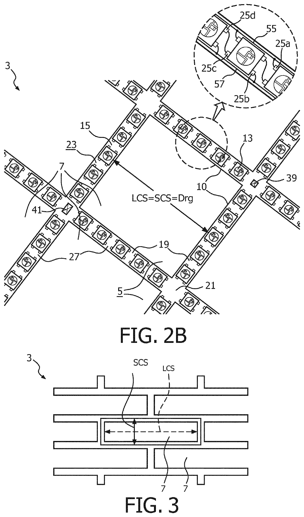
[0042]FIG. 3 shows a part of a grid sheet carrier 3 according to the invention in which the grid sheet carrier has a ratio CSr between the largest LCS and smallest cross section SCS of each opening 7 of about four, i.e. well within the ratio of 1

[0043]FIG. 4A-C shows three illustrative examples of (dynamic) light patterns 29 obtained by the lighting device 1 according to the invention in an installed, operating state. The lighting device has regular grid 3 mounted with a part of its border 4 on a base part 2 and on which grid the LEDs (not shown / visible) are mounted and which...


PUM

PropertyMeasurementUnit
apex angleaaaaaaaaaa

Abstract

A lighting device comprising a grid sheet carrier 3 mounted via its border 4 on a base part and having an open surface area 5 of a plurality of openings 7 and having carrier material 9 surrounding said openings. The carrier material 9 being arranged in a two-dimensional, first pattern 11. The lighting device further comprises a plurality of LEDs 13 mounted on one main face 15 of the carrier material 9 and arranged in a two-dimensional, second pattern 17. The second pattern 17 is coinciding with the first pattern 11 when superimposed and the second pattern 17 is at least a sub-pattern of the first pattern 11. Furthermore, R is a ratio between the plurality of LEDs 13 and the plurality of openings 7, wherein R>=3.

Description

CROSS-REFERENCE TO PRIOR APPLICATIONS[0001]This application is the U.S. National Phase application under 35 U.S.C. § 371 of International Application No. PCT / EP2016 / 073544, filed on Oct. 3, 2016, which claims the benefit of European Patent Application No. 15189086.0, filed on Oct. 9, 2015. These applications are hereby incorporated by reference herein.TECHNICAL FIELD[0002]The invention relates to a lighting device comprising LEDs mounted on a grid sheet carrier.TECHNICAL BACKGROUND[0003]Ledification of many light sources and systems is nearly done. Almost all conventional products are replaced by LED versions. The first generation LED based lighting was based on so called high power LEDs. This is in comparison to LEDs used for signaling, for example on / off indicators. A high-power LED is a LED with over 1 watt energy consumption. More recently, the use of low- or mid-power LEDs seems even more attractive as, although these light sources produce less light, the lumen per dollar ratio...

Claims


Application Information

Patent Timeline
Patent Type & Authority Patents(United States)
IPC IPC(8): F21S6/00F21V23/00F21S10/02F21Y105/10F21Y113/13F21Y113/17F21Y115/10
CPCF21V23/001F21S6/00F21Y2113/17F21Y2105/10F21Y2113/13F21Y2115/10F21S10/023
Inventor BERGMAN, ANTHONIE HENDRIKDEKKER, TIMVAN GHELUWE, JOCHEN RENAATDE ZWART, SIEBE TJERK
Owner SIGNIFY HLDG BV
Why Eureka
Try Eureka