
Teleconverter optical system

a technology of optical systems and converters, applied in the field of converter optical systems, can solve the problems of optical zoom functions having difficulty in obtaining the desired zoom ratio, low resolution of digital zoom functions,

Active Publication Date: 2020-04-21
SAMSUNG ELECTRO MECHANICS CO LTD
View PDF24 Cites 1 Cited by
  • Summary
  • Abstract
  • Description
  • Claims
  • Application Information

AI Technical Summary

Benefits of technology

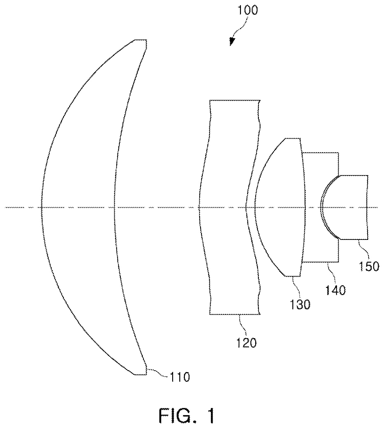
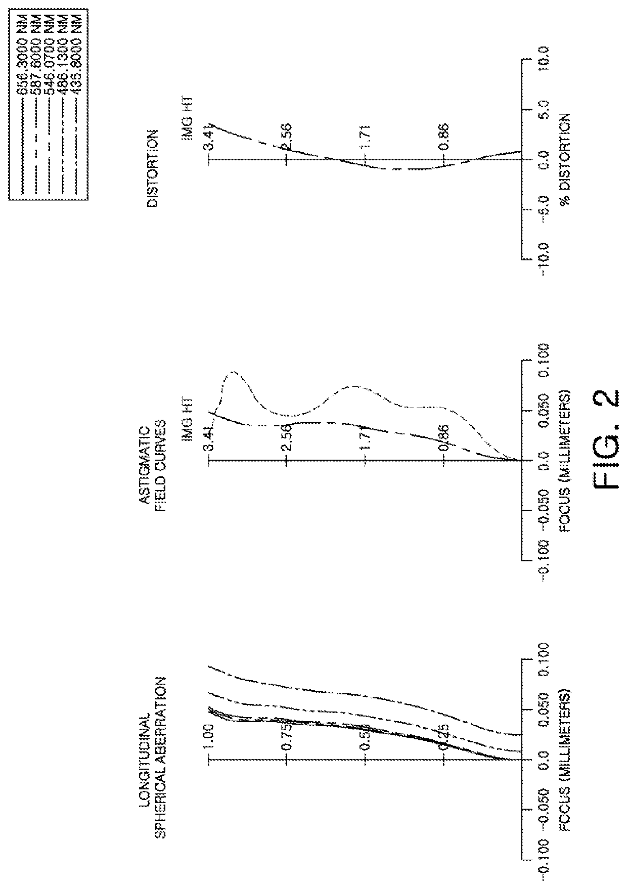
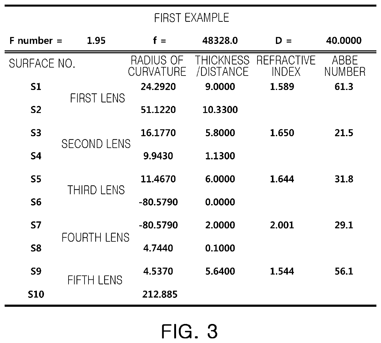
[0071]A converter optical system satisfying the above Conditional Expressions may be miniaturized. In addition, a converter optical system satisfying the above Conditional Expressions may clearly image a subject positioned at a long distance.

Problems solved by technology

However, the digital zoom function has a very low level of resolution, and the optical zoom function has a difficulty in obtaining a desired zoom ratio due to a limitation of sizes of portable terminals.

Method used


Image

  • Teleconverter optical system
  • Teleconverter optical system
  • Teleconverter optical system

Examples


Embodiment Construction

[0040]The following detailed description is provided to assist the reader in gaining a comprehensive understanding of the methods, apparatuses, and / or systems described herein. However, various changes, modifications, and equivalents of the methods, apparatuses, and / or systems described herein will be apparent after an understanding of the disclosure of this application. For example, the sequences of operations described herein are merely examples, and are not limited to those set forth herein, but may be changed as will be apparent after an understanding of the disclosure of this application, with the exception of operations necessarily occurring in a certain order. Also, descriptions of features that are known in the art may be omitted for increased clarity and conciseness.

[0041]The features described herein may be embodied in different forms, and are not to be construed as being limited to the examples described herein. Rather, the examples described herein have been provided mer...


PUM


Abstract

A converter optical system includes a first lens having positive refractive power; a second lens having negative refractive power; a third lens having positive refractive power; a fourth lens having negative refractive power; and a fifth lens having positive refractive power; wherein the first to fifth lenses are sequentially disposed in numerical order from the first lens to the fifth lens from an object side of the converter optical system to an image side of the converter optical system; and the fourth lens is bonded to either one or both of the third lens and the fifth lens.

Description

CROSS-REFERENCE TO RELATED APPLICATIONS[0001]This application claims the benefit under 35 USC 119(a) of Korean Patent Application No. 10-2016-0009794 filed on Jan. 27, 2016, in the Korean Intellectual Property Office, the entire disclosure of which is incorporated herein by reference for all purposes.BACKGROUND1. Field[0002]This application relates to a converter optical system.2. Description of Related Art[0003]A small camera module mounted in a portable terminal is very small. The small camera module has a fixed focus, and may thus image only a subject positioned at a short distance therefrom. Some small camera modules may image a subject positioned at a far distance therefrom through a digital zoom function or an optical zoom function. However, the digital zoom function has a very low level of resolution, and the optical zoom function has a difficulty in obtaining a desired zoom ratio due to a limitation of sizes of portable terminals.SUMMARY[0004]This summary is provided to intr...

Claims


Application Information

Patent Timeline
Patent Type & Authority Patents(United States)
IPC IPC(8): G02B15/12G02B13/00
CPCG02B15/12G02B13/001G02B13/0045G02B13/18
Inventor KO, JUNG HUI
Owner SAMSUNG ELECTRO MECHANICS CO LTD
Learn More