
Method for monitoring functional states a pressure driven actuator and pressure-actuatable actuator

a technology of functional state monitoring and actuator, which is applied in the direction of load-engaging elements, program-controlled manipulators, gearing elements, etc., can solve the problems of increasing structural complexity, increasing susceptibility to errors, and changing mechanical properties of actuators over time, so as to achieve reliable monitoring of functional states

Active Publication Date: 2020-04-28
J SCHMALZ GMBH
View PDF57 Cites 1 Cited by
  • Summary
  • Abstract
  • Description
  • Claims
  • Application Information

AI Technical Summary

Benefits of technology

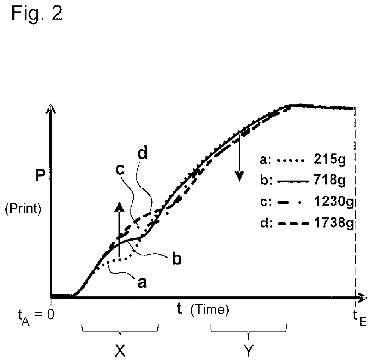
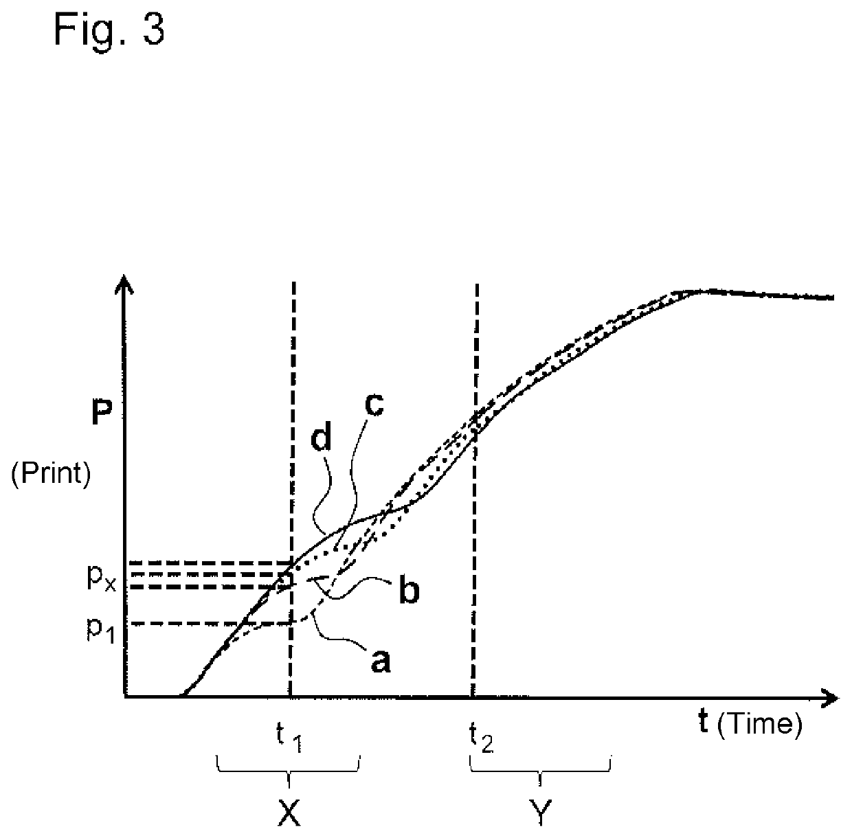
The present invention provides a method for reliably monitoring the functional state of a pressure-driven actuator in a simple manner using just one sensor apparatus. This method can determine various types of information using just one sensor, reducing the susceptibility to errors and allowing for better control of the actuator. The monitoring can be carried out under the effect of a load, without interrupting the intended use. The method also allows for the determination of the change in the measured pressure over time, which can be used to evaluate the work process and prevent damage or deformation. The method can also store a characteristic curve representing the progression of the pressure over time, which can help in analyzing the influence of different factors on the actuator's function.

Problems solved by technology

First of all, the mechanical properties of the actuators may change over time, e.g. due to ageing or wear of the materials used.
In order to monitor various types of functional state, a plurality of sensors comprising associated data communication and control are required, and this can lead to increased structural complexity and increased susceptibility to errors.

Method used


Image

  • Method for monitoring functional states a pressure driven actuator and pressure-actuatable actuator
  • Method for monitoring functional states a pressure driven actuator and pressure-actuatable actuator
  • Method for monitoring functional states a pressure driven actuator and pressure-actuatable actuator

Examples


Embodiment Construction

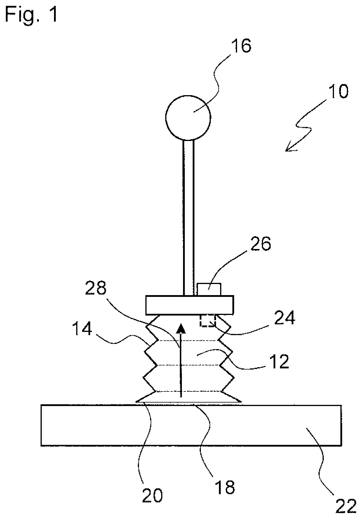
[0051]FIG. 1 is a schematic view of a pressure-driven actuator 10. The actuator 10 is only designed as a vacuum pick-up device by way of example. The actuator comprises an actuator compartment 12 defined by a flexibly deformable wall 14. In the example shown, the flexibly deformable wall is designed as a flexibly deformable bellows 14.

[0052]In order for pressure to be applied to the actuator compartment 12, the actuator compartment 12 is in a pressure connection and / or flow connection with an operating pressure supply 16.

[0053]The actuator 10, which is designed as a vacuum pick-up device in FIG. 1, comprises a contact surface 18 comprising a suction opening 20 that communicates with the actuator compartment 12. In order to pick up an object 22, the contact surface 18 comprising the suction opening is brought into contact with the object 22 and a vacuum is applied to the actuator compartment 12.

[0054]However, actuators comprising other types of actuator compartment 12 can also be use...


PUM


Abstract

The invention relates to a method for monitoring a functional state of a pressure-driven actuator which comprises an actuator compartment defined at least in portions by a flexibly deformable wall, the actuator being actuated by applying pressure to the actuator compartment by means of an operating pressure supply, a work process being carried out to actuate the actuator, which process is accompanied by the actuator transitioning from a starting configuration to an end configuration. The pressure the pressure applied to the actuator compartment is measured depending on time by means of a sensor apparatus during the transition from the starting configuration to the end configuration. The invention also relates to a pressure-driven actuator.

Description

CROSS-REFERENCE TO RELATED APPLICATIONS[0001]This application relates and claims priority to European Application No. 16168786.8-1807, filed May 9, 2016, the entire disclosure of which is incorporated herein by reference.BACKGROUND OF THE INVENTION[0002]The invention relates to a method for monitoring functional states of a pressure-driven actuator, and to a pressure-drivable actuator.[0003]One field of application concerns vacuum-driven actuators, e.g. vacuum pick-up devices, expansion bellows or vacuum tube lifters comprising vacuum lifting tubes, as described e.g. in WO 2005 / 110907 A1 or U.S. Pat. No. 4,413,853 A. Another field of application concerns overpressure-driven actuators, e.g. pneumatic or hydraulic actuators or manipulators.[0004]Actuators of this type have in common that pressure is applied to a flexibly deformable actuator compartment in order to actuate the actuator. In this case, in principle this may relate to overpressure (for overpressure-driven actuators) or a ...

Claims


Application Information

Patent Timeline
Patent Type & Authority Patents(United States)
IPC IPC(8): F16H61/00B25J15/06B25J15/12F16H61/433F16H61/4017B25J9/14F16H59/68B25J13/08B25J15/00
CPCB25J9/142B25J15/0616B25J13/087F16H61/4017B25J15/0023F16H61/433F16H61/0021B25J15/12F16H2061/0046F16H2061/0034F16H2061/0075F16H2059/6861B25J15/0675B25J15/0683B25J19/02B66C1/0256B66C1/0293B66C1/46B66C13/16
Inventor DEFRANCESKI, ALINEDUNKMANN, WALTER
Owner J SCHMALZ GMBH
Learn More