Sputtering target and process for production thereof

a technology of sputtering target and production process, which is applied in the direction of electrical apparatus, basic electric elements, metal material coating process, etc., can solve the problems of loss of recorded signals, major obstacle to increasing the recording density of magnetic disks, and affecting the thermal stability of recorded signals, etc., to achieve high coercive force hc

Active Publication Date: 2020-04-28
TANAKA PRECIOUS METAL IND +1
View PDF9 Cites 1 Cited by
  • Summary
  • Abstract
  • Description
  • Claims
  • Application Information

AI Technical Summary

Benefits of technology

[0034]The present invention can provide a sputtering target with which it is possible to form a magnetic thin film having a high coercive force Hc and provide a process for production thereof.
[0035]Also, the present invention can provide a sputtering target with which it is possible to form a magnetic thin film whose coercive force Hc can be increased by annealing and provide a process for production thereof.

Problems solved by technology

However, the progress of micronization of magnetic crystal grains has resulted in occurrence of the so-called thermal fluctuation phenomenon, in which the superparamagnetic phenomenon impairs the thermal stability of recorded signals and leads to loss of the recorded signals.
This thermal fluctuation phenomenon has contributed a major obstacle to increasing the recording density of magnetic disks.
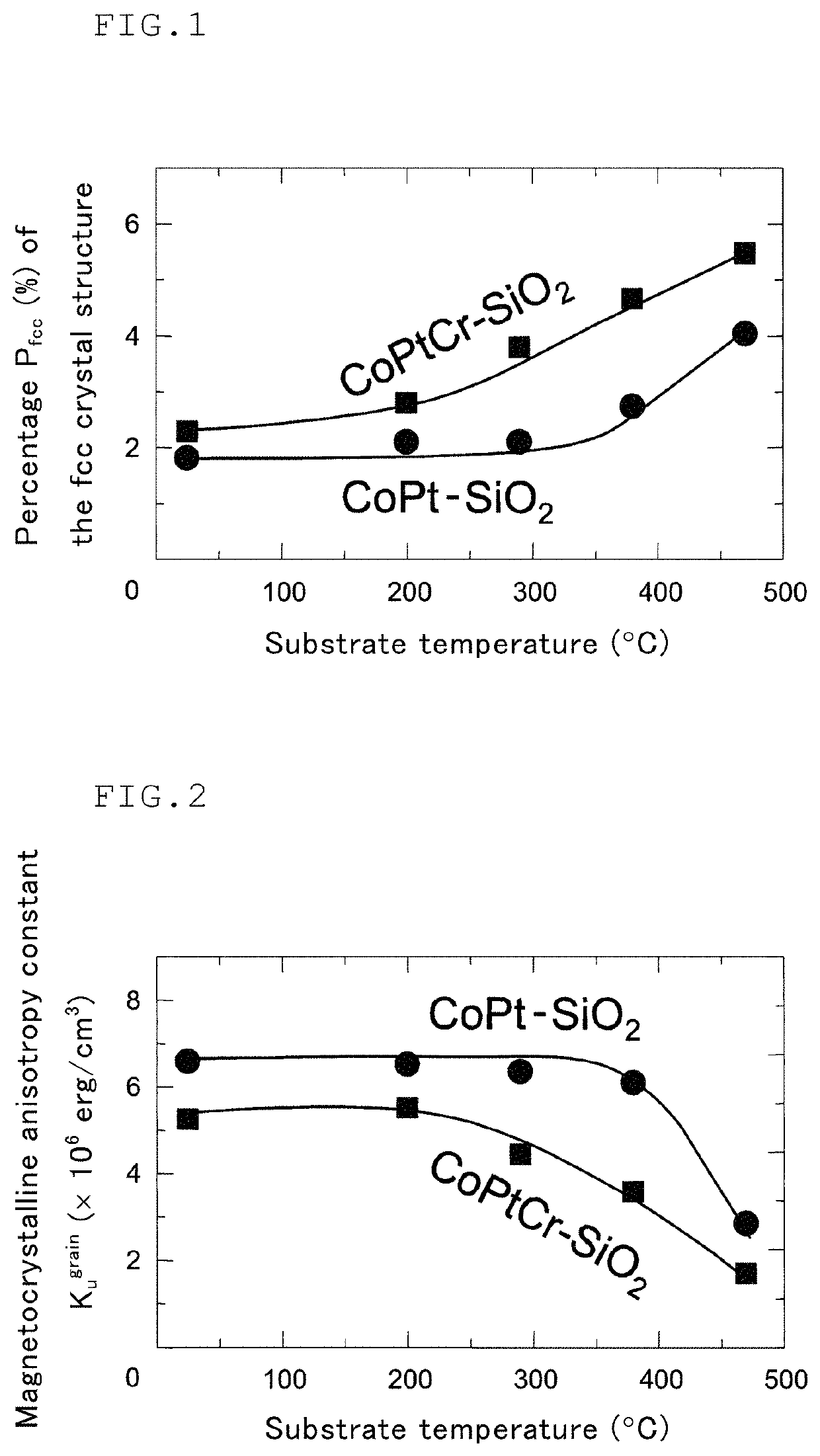
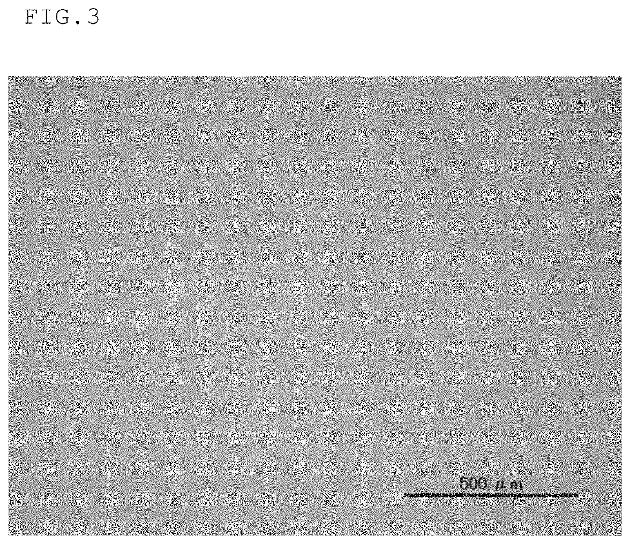
However, annealing has increased the diameter of the lower portions (portions near the substrate) of columnar CoPtCr magnetic crystal grains and has caused magnetic coupling in the lower portions of the CoPtCr magnetic crystal grains.

Method used


Image

  • Sputtering target and process for production thereof
  • Sputtering target and process for production thereof
  • Sputtering target and process for production thereof

Examples


example 1

[0083]The composition of the entire target prepared as Example 1 is 91.4 (80Co-20Pt)-8.6WO3 in terms of molar ratio. The target was prepared and evaluated in the following manner. The composition of the entire target prepared in Example 1, when the content percentage of the oxide (WO3) is expressed as the volume fraction in the entire target, is (80Co-20Pt)-30 vol % WO3. The target prepared in Example 1 is within the scope of the target according to the present invention.

[0084]To prepare the target according to Example 1, an 80Co-20Pt alloy-atomized powder was prepared first. Specifically, metals were weighed so as to obtain an alloy composition of Co: 80 at % and Pt: 20 at % and heated to 1500° C. or higher to prepare a molten alloy. The molten alloy was gas-atomized to prepare an 80Co-20Pt alloy-atomized powder.

[0085]The prepared 80Co-20Pt alloy-atomized powder was separately classified through 150 mesh sieves to obtain 80Co-20Pt alloy-atomized powder having a particle diameter of...

example 2

[0100]The composition of the entire target prepared as Example 2 is (80Co-20Pt)-30 vol % TiO2. A target was prepared in the same manner as in Example 1 except that TiO2 was used as an oxide. The target prepared in Example 2 is within the scope of the target according to the present invention. Samples for determining magnetic properties were also prepared in the same manner as in Example 1 using the prepared target.

[0101]In the same manner as in Example 1, the M-H loops (magnetization curves) were obtained by using a magneto-optical Kerr effect apparatus for samples (total six samples) for determining magnetic properties that had been annealed at target annealing temperatures (200° C., 300° C., 400° C., 450° C., 500° C., and 600° C.) and cooled to room temperature and a sample (one sample) for determining magnetic properties that had not been annealed after film deposition at room temperature. The coercive force Hc was read from each M-H loop (magnetization curve).

[0102]The measured ...


PUM

PropertyMeasurementUnit
volume fractionaaaaaaaaaa
vol %aaaaaaaaaa

Abstract

Provided is a sputtering target with which it is possible to form a magnetic thin film having a high coercive force Hc and a process for production thereof. The sputtering target is a sputtering target comprising metallic Co, metallic Pt, and an oxide, wherein the sputtering target does not contain metallic Cr, and the oxide is WO3 and wherein the sputtering target comprises 25 to 50 at % of metallic Co relative to a total of metallic Co and metallic Pt.

Description

TECHNICAL FIELD[0001]The present invention relates to a sputtering target and a process for production thereof. More particularly, the present invention relates to a sputtering target with which it is possible to form a magnetic thin film having a high coercive force and to a process for production thereof. Hereinafter, the sputtering target may be referred to simply as a “target”.BACKGROUND ART[0002]A magnetic disk in a hard disk drive utilizes a magnetic thin film having a CoPtCr-oxide-based granular structure as a magnetic recording film that records information signals (for example, see Non-Patent Literature 1). In order to further improve the recording density of this magnetic thin film, there is a need to micronize magnetic crystal grains contained in the magnetic recording layer (magnetic thin film).[0003]However, the progress of micronization of magnetic crystal grains has resulted in occurrence of the so-called thermal fluctuation phenomenon, in which the superparamagnetic ...

Claims


Application Information

Patent Timeline
Patent Type & Authority Patents(United States)
IPC IPC(8): C23C14/34C22F1/14C22F1/10C23C14/58C23C14/06C22C1/10C22C1/05C22C19/07C22C5/04H01J37/34C23C14/08C23C14/14C22C1/04C04B35/00B22F3/14B22F9/04B22F9/08
CPCC23C14/3414C23C14/0688C22C1/05C22C1/1084C23C14/083C23C14/14C22C1/0466C22F1/10C22F1/14H01J37/3429C04B35/00C22C19/07C22C5/04H01J37/3426C23C14/5806B22F2998/10B22F2301/15B22F9/082B22F2301/25B22F2302/25B22F9/04B22F2999/00C22C2202/02B22F3/14
Inventor THAM, KIM KONGYAMAMOTO, TOSHIYASAITO, SHINHINATA, SHINTAROTAKAHASHI, MIGAKU
Owner TANAKA PRECIOUS METAL IND
Why Eureka
Try Eureka